4.1ASSEMBLY INSTRUCTIONS FOR 61" CUTTER DECKS
Use the illustrated parts list as a part
number reference when following the assembly instructions.
1.Remove all packaging materials. Lay out the mounting hardware and the catcher assembly parts for easy access. Prepare the work area making sure that it is a clean, safe environment.
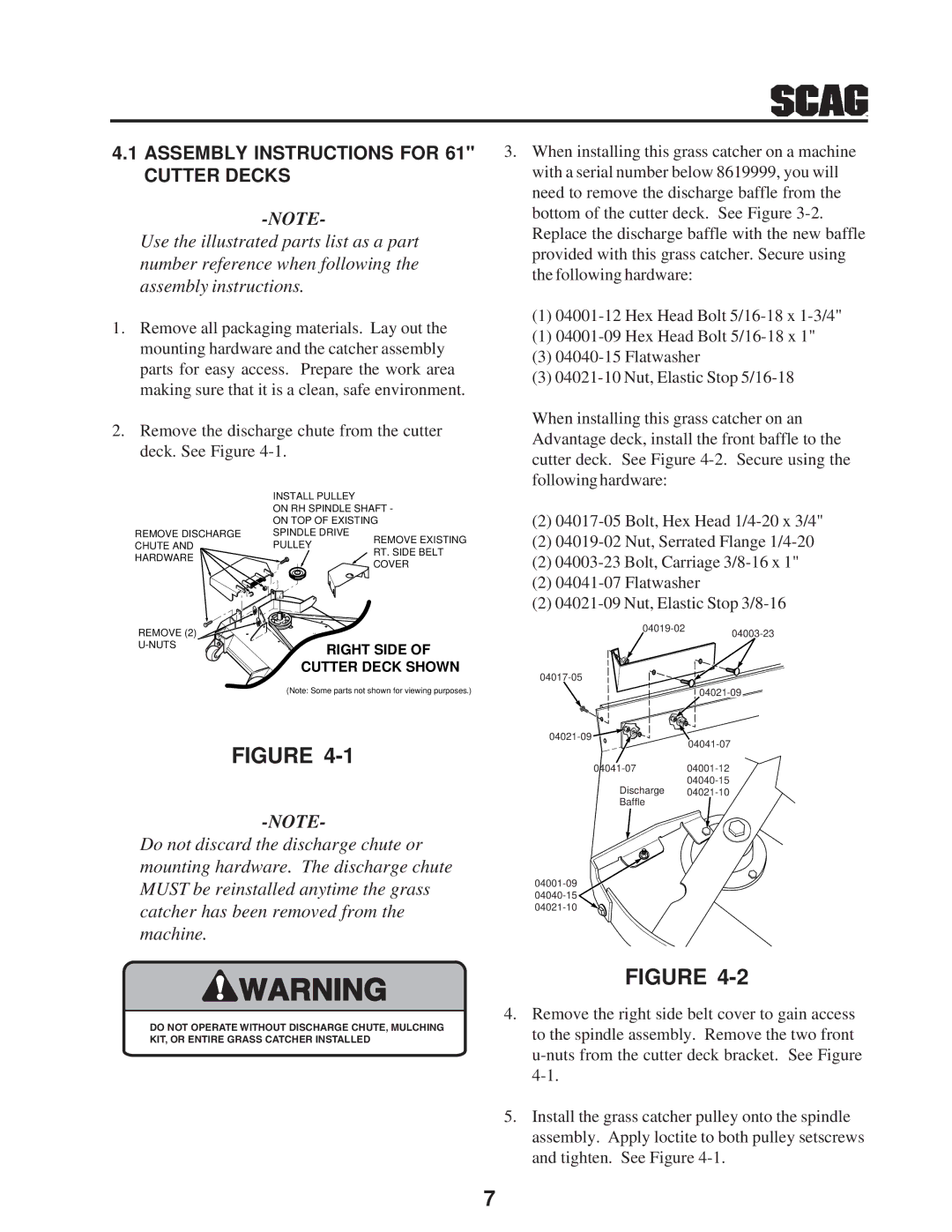
2.Remove the discharge chute from the cutter deck. See Figure
3.When installing this grass catcher on a machine with a serial number below 8619999, you will need to remove the discharge baffle from the bottom of the cutter deck. See Figure
(1)
(1)
(3)
(3)
When installing this grass catcher on an Advantage deck, install the front baffle to the cutter deck. See Figure
REMOVE DISCHARGE CHUTE AND HARDWARE
REMOVE (2)![]()
INSTALL PULLEY
ON RH SPINDLE SHAFT -
ON TOP OF EXISTING
SPINDLE DRIVE
PULLEY | REMOVE EXISTING | |
RT. SIDE BELT | ||
| ||
| COVER |
RIGHT SIDE OF
CUTTER DECK SHOWN
(2)
(2)
(2)
(2)
(2)
(Note: Some parts not shown for viewing purposes.)
FIGURE
Do not discard the discharge chute or mounting hardware. The discharge chute MUST be reinstalled anytime the grass catcher has been removed from the machine.
![]()
![]()
![]()
![]() 04041-07
04041-07
Discharge
![]() WARNING
WARNING
DO NOT OPERATE WITHOUT DISCHARGE CHUTE, MULCHING KIT, OR ENTIRE GRASS CATCHER INSTALLED
FIGURE
4.Remove the right side belt cover to gain access to the spindle assembly. Remove the two front
5.Install the grass catcher pulley onto the spindle assembly. Apply loctite to both pulley setscrews and tighten. See Figure
7