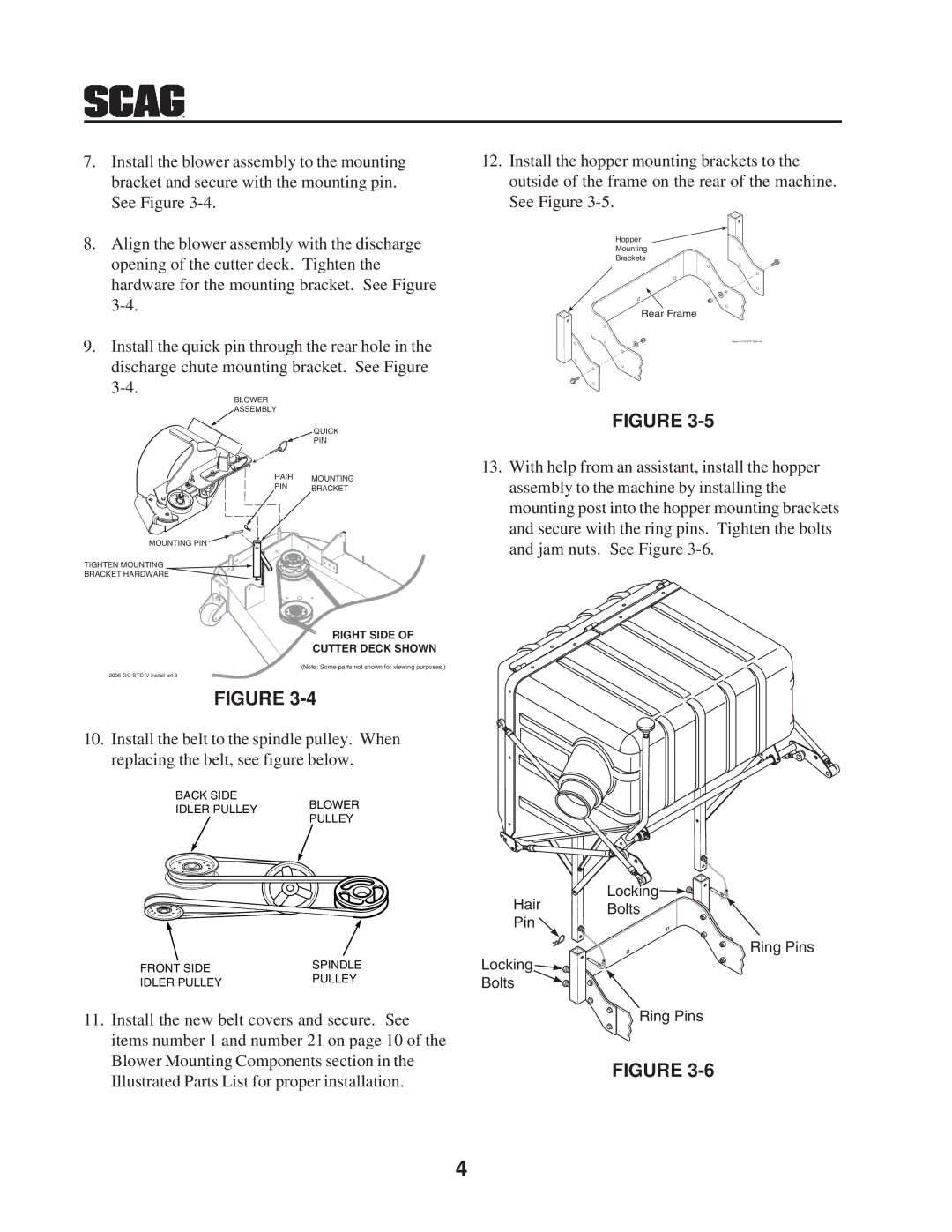
7.Install the blower assembly to the mounting bracket and secure with the mounting pin. See Figure
8.Align the blower assembly with the discharge opening of the cutter deck. Tighten the hardware for the mounting bracket. See Figure
9.Install the quick pin through the rear hole in the discharge chute mounting bracket. See Figure
BLOWER
ASSEMBLY
QUICK
PIN
HAIR MOUNTING
PIN BRACKET
MOUNTING PIN
TIGHTEN MOUNTING ![]()
BRACKET HARDWARE
RIGHT SIDE OF
CUTTER DECK SHOWN
(Note: Some parts not shown for viewing purposes.)
2006 GC-STC-V install art 3
FIGURE
10.Install the belt to the spindle pulley. When replacing the belt, see figure below.
BACK SIDE
IDLER PULLEY BLOWER
PULLEY
12.Install the hopper mounting brackets to the outside of the frame on the rear of the machine. See Figure
Hopper
Mounting
Brackets
Rear Frame
Figure 4 A GC-STT Install Art
FIGURE
13.With help from an assistant, install the hopper assembly to the machine by installing the mounting post into the hopper mounting brackets and secure with the ring pins. Tighten the bolts and jam nuts. See Figure
FRONT SIDE | SPINDLE | |
PULLEY | ||
IDLER PULLEY | ||
|
11.Install the new belt covers and secure. See items number 1 and number 21 on page 10 of the Blower Mounting Components section in the Illustrated Parts List for proper installation.
Hair | Locking | |
Bolts | ||
Pin | ||
| ||
| Ring Pins | |
Locking |
| |
Bolts |
|
![]() Ring Pins
Ring Pins
FIGURE
4
