Windows XP, Windows Me, Windows 98 or newer versions are needed to support drives with capacities greater than 32 Gbytes.
3.3.4Ultra ATA/100 cable
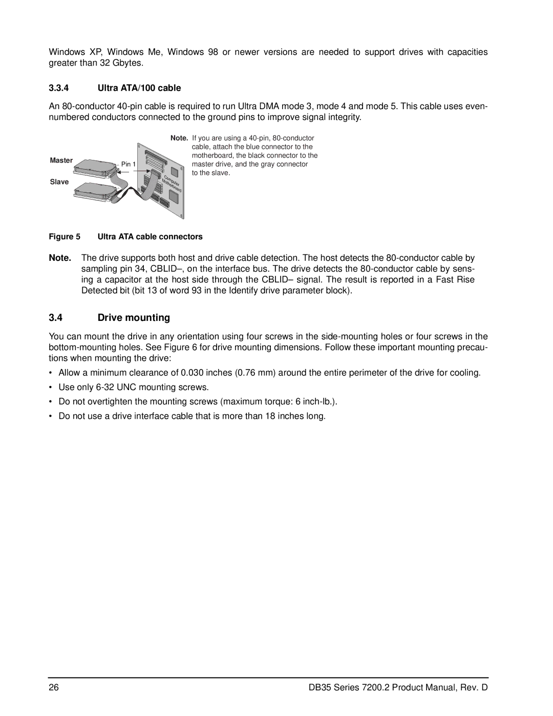
An 80-conductor 40-pin cable is required to run Ultra DMA mode 3, mode 4 and mode 5. This cable uses even- numbered conductors connected to the ground pins to improve signal integrity.
| Note. |
Master | Pin 1 |
|
Slave | Computer |
| Motherboard |
If you are using a 40-pin, 80-conductor cable, attach the blue connector to the motherboard, the black connector to the master drive, and the gray connector to the slave.
Figure 5 Ultra ATA cable connectors
Note. The drive supports both host and drive cable detection. The host detects the 80-conductor cable by sampling pin 34, CBLID–, on the interface bus. The drive detects the 80-conductor cable by sens- ing a capacitor at the host side through the CBLID– signal. The result is reported in a Fast Rise Detected bit (bit 13 of word 93 in the Identify drive parameter block).
3.4Drive mounting
You can mount the drive in any orientation using four screws in the side-mounting holes or four screws in the bottom-mounting holes. See Figure 6 for drive mounting dimensions. Follow these important mounting precau- tions when mounting the drive:
•Allow a minimum clearance of 0.030 inches (0.76 mm) around the entire perimeter of the drive for cooling.
•Use only 6-32 UNC mounting screws.
•Do not overtighten the mounting screws (maximum torque: 6 inch-lb.).
•Do not use a drive interface cable that is more than 18 inches long.
26 | DB35 Series 7200.2 Product Manual, Rev. D |