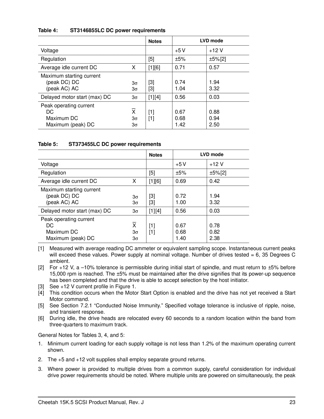
Table 4: | ST3146855LC DC power requirements |
|
|
| |||
|
|
|
|
|
|
|
|
|
|
|
| Notes |
| LVD mode | |
|
|
|
|
|
|
|
|
Voltage |
|
|
|
| +5 V |
| +12 V |
|
|
|
|
|
|
|
|
Regulation |
|
|
| [5] | ±5% |
| ±5%[2] |
|
|
|
|
|
| ||
Average idle current DC | X | [1][6] | 0.71 |
| 0.57 | ||
|
|
|
|
|
|
| |
Maximum starting current |
|
|
|
|
|
| |
(peak DC) DC | 3σ | [3] | 0.74 |
| 1.94 | ||
(peak AC) AC | 3σ | [3] | 1.04 |
| 3.32 | ||
Delayed motor start (max) DC | 3σ | [1][4] | 0.56 |
| 0.03 | ||
|
|
|
|
|
|
| |
Peak operating current |
|
|
|
|
|
| |
DC |
| X |
| [1] | 0.67 |
| 0.88 |
Maximum DC | 3σ | [1] | 0.68 |
| 0.94 | ||
Maximum (peak) DC | 3σ |
| 1.42 |
| 2.50 | ||
|
|
|
|
|
|
|
|
Table 5: | ST373455LC DC power requirements |
|
|
| |||
|
|
|
|
|
|
|
|
|
|
|
| Notes |
| LVD mode | |
|
|
|
|
|
|
|
|
Voltage |
|
|
|
| +5 V |
| +12 V |
|
|
|
|
|
|
|
|
Regulation |
|
|
| [5] | ±5% |
| ±5%[2] |
|
|
|
|
|
| ||
Average idle current DC | X | [1][6] | 0.69 |
| 0.42 | ||
|
|
|
|
|
|
| |
Maximum starting current |
|
|
|
|
|
| |
(peak DC) DC | 3σ | [3] | 0.72 |
| 1.94 | ||
(peak AC) AC | 3σ | [3] | 1.00 |
| 3.32 | ||
Delayed motor start (max) DC | 3σ | [1][4] | 0.56 |
| 0.03 | ||
|
|
|
|
|
|
| |
Peak operating current |
|
|
|
|
|
| |
DC |
| X |
| [1] | 0.67 |
| 0.78 |
Maximum DC | 3σ | [1] | 0.68 |
| 0.82 | ||
Maximum (peak) DC | 3σ |
| 1.40 |
| 2.38 | ||
|
|
|
|
|
|
|
|
[1]Measured with average reading DC ammeter or equivalent sampling scope. Instantaneous current peaks will exceed these values. Power supply at nominal voltage. Number of drives tested = 6, 35 Degrees C ambient.
[2]For +12 V, a
[3]See +12 V current profile in Figure 1.
[4]This condition occurs when the Motor Start Option is enabled and the drive has not yet received a Start Motor command.
[5]See Section 7.2.1 “Conducted Noise Immunity.” Specified voltage tolerance is inclusive of ripple, noise, and transient response.
[6]During idle, the drive heads are relocated every 60 seconds to a random location within the band from
General Notes for Tables 3, 4, and 5:
1.Minimum current loading for each supply voltage is not less than 1.2% of the maximum operating current shown.
2.The +5 and +12 volt supplies shall employ separate ground returns.
3.Where power is provided to multiple drives from a common supply, careful consideration for individual drive power requirements should be noted. Where multiple units are powered on simultaneously, the peak
Cheetah 15K.5 SCSI Product Manual, Rev. J | 23 |