LVD Input characteristics
Each differential signal received by LVD interface receiver circuits shall have the following input characteristics when measured at the disc drive connector:
Steady state Low level input differential voltage = 0.030 V = < Vin = < 3.6 V (signal negation/logic 0) Steady state High level input differential voltage =
| VCCA |
| VCCB |
Single | LVD Signal Drivers | Single | Single |
| |||
Ended |
| Ended | Ended |
Circuitry |
| Receiver | Negation |
| LVD |
| Driver |
| Receiver |
|
|
Single |
|
| Single |
Ended |
|
| Ended |
Ground |
|
| Assertion |
Driver |
|
| Driver |
| LVD Signal Drivers |
|
|
Ground |
|
|
|
Single Ended: | GND | |
LVD: | +Signal |
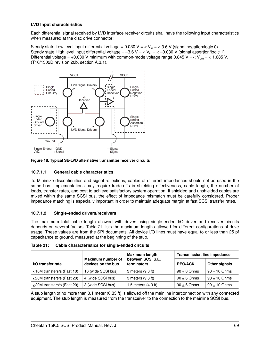
Figure 18. Typical SE-LVD alternative transmitter receiver circuits
10.7.1.1General cable characteristics
To Minimize discontinuities and signal reflections, cables of different impedances should not be used in the same bus. Implementations may require
10.7.1.2Single-ended drivers/receivers
The maximum total cable length allowed with drives using
Table 21: Cable characteristics for single-ended circuits
|
| Maximum length | Transmission line impedance | |
| Maximum number of | between SCSI S.E. |
|
|
|
|
| ||
I/O transfer rate | devices on the bus | terminators | REQ/ACK | Other signals |
|
|
|
|
|
<10M transfers/s (Fast 10) | 16 (wide SCSI bus) | 3 meters (9.8 ft) | 90 + 6 Ohms | 90 + 10 Ohms |
|
|
|
|
|
<20M transfers/s (Fast 20) | 4 (wide SCSI bus) | 3 meters (9.8 ft) | 90 + 6 Ohms | 90 + 10 Ohms |
|
|
|
|
|
<20M transfers/s (Fast 20) | 8 (wide SCSI bus) | 1.5 meters (4.9 ft) | 90 + 6 Ohms | 90 + 10 Ohms |
|
|
|
|
|
A stub length of no more than 0.1 meter (0.33 ft) is allowed off the mainline interconnection with any connected equipment. The stub length is measured from the transceiver to the connection to the mainline SCSI bus.
Cheetah 15K.5 SCSI Product Manual, Rev. J | 69 |