ST3160215SCE, ST380215ACE, ST380215SCE, ST3160215ACE specifications
Seagate has long been a prominent name in the world of hard drives, known for their innovative technology and reliable performance. Among their extensive product lineup, the Seagate ST3160215ACE, ST380215SCE, ST380215ACE, and ST3160215SCE hard drives stand out for their robust features and capabilities, catering to both personal and enterprise-level needs.The Seagate ST3160215ACE offers a capacity of 160 GB, while the ST380215SCE and ST380215ACE provide 80 GB of storage. These drives are renowned for their performance, equipped with a SATA interface that ensures fast data transfer rates and efficient connectivity. With spindle speeds of 7200 RPM, these models benefit from lower latency and higher data throughput, making them suitable for a variety of applications, including gaming, media storage, and data backup.
One of the defining characteristics of the Seagate ST3160215ACE and its counterparts is their reliable data integrity features. These drives incorporate Seagate's advanced error correction technologies, including S.M.A.R.T. (Self-Monitoring, Analysis, and Reporting Technology), which enables users to predict drive failures before they occur. This technology significantly reduces the risk of data loss, ensuring that important files remain secure.
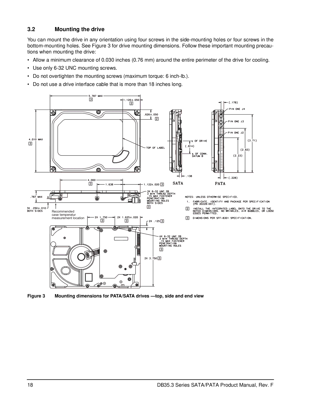
In terms of physical design, the drives feature a compact 3.5-inch form factor, making them ideal for both desktop computers and external enclosures. The drives are built with Seagate's durable engineering, offering resilience against shock and vibration, which is essential for maintaining performance in various environmental conditions.
These models also employ a low power consumption strategy, which not only reduces energy costs but also extends the lifespan of the drive. By utilizing advanced power management technologies, the drives efficiently handle thermal conditions, ensuring stable operation even during prolonged usage.
Additionally, their compatibility with various operating systems and RAID configurations enhances their versatility in new and existing systems. Whether for a home PC or within an enterprise server setup, these Seagate models deliver performance and reliability, solidifying their place in the storage market. In summary, the Seagate ST3160215ACE, ST380215SCE, ST380215ACE, and ST3160215SCE drives offer a combination of capacity, speed, reliability, and energy efficiency, making them a compelling choice for users seeking dependable storage solutions.

