4.2Parallel ATA (PATA) Interface

These drives use the industry-standard ATA task file interface that supports 16-bit data transfers. It supports ATA programmed input/output (PIO) modes 0–4; multiword DMA modes 0–2, and Ultra DMA modes 0–5. The drive also supports the use of the IORDY signal to provide reliable high-speed data transfers.

You can use a daisy-chain cable to connect two drives to a single AT host bus. For detailed information about the ATA interface, refer to the draft of AT Attachment with Packet Interface Extension (ATA/ATAPI-7), NCITS T13 1410D, subsequently referred to as the Draft ATA-7 Standard.

4.2.1ATA interface signals and connector pins

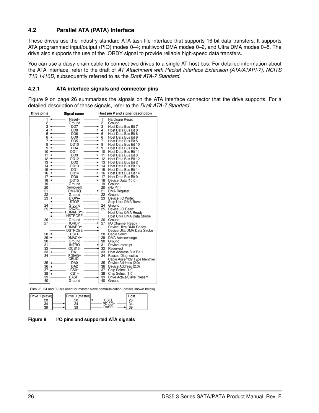
Figure 9 on page 26 summarizes the signals on the ATA interface connector that the drive supports. For a detailed description of these signals, refer to the Draft ATA-7 Standard.

Drive pin #


Signal name


Host pin # and signal description

1


Reset–


1

Hardware Reset


2


Ground

2

Ground

3


DD7


3

Host Data Bus Bit 7


4


DD8


4

Host Data Bus Bit 8


5


DD6


5

Host Data Bus Bit 6


6


DD9


6

Host Data Bus Bit 9


7


DD5


7

Host Data Bus Bit 5


8


DD10


8

Host Data Bus Bit 10


9


DD4


9

Host Data Bus Bit 4


10


DD11


10

Host Data Bus Bit 11


11


DD3


11

Host Data Bus Bit 3


12


DD12


12

Host Data Bus Bit 12


13


DD2


13

Host Data Bus Bit 2


14


DD13


14

Host Data Bus Bit 13


15


DD1


15

Host Data Bus Bit 1


16


DD14


16

Host Data Bus Bit 14


17


DD0


17

Host Data Bus Bit 0


18


DD15


18

Device Data (15:0)


19


Ground

19

Ground

20


(removed)

20

(No Pin)

21


DMARQ


21

DMA Request


22


Ground

22

Ground

23


DIOW–


23

Device I/O Write:


STOP


Stop Ultra DMA Burst


24


Ground

24

Ground

25


DIOR–


25

Device I/O Read:


HDMARDY–


Host Ultra DMA Ready:


HSTROBE


Host Ultra DMA Data Strobe


26


Ground

26

Ground

27


IORDY


27

I/O Channel Ready


DDMARDY–


Device Ultra DMA Ready


DSTROBE


Device Ulta DMA Data Strobe


28


CSEL


28

Cable Select


29


DMACK–


29

DMA Acknowledge


30


Ground

30

Ground

31INTRQ 31 Device Interrupt

32IOCS16– 32 Reserved

33


DA1


33

Host Address Bus Bit 1

34


PDIAG–


34

Passed Diagnostics


CBLID–


Cable Assembly Type Identifier

35


DA0


35

Device Address (2:0)


36


DA2


36

Device Address (2:0)

37


CS0–


37

Chip Select (1:0)

38


CS1–


38

Chip Select (1:0)

39


DASP–


39

Drive Active/Slave Present

40


Ground

40

Ground

Pins 28, 34 and 39 are used for master-slave communication (details shown below).

Drive 1 (slave)

28

34

39

Drive 0 (master)

28

34

39

CSEL

PDIAG–

DASP–

Host

28

34

39

Figure 9 I/O pins and supported ATA signals

26

DB35.3 Series SATA/PATA Product Manual, Rev. F

Page 32
Image 32
Seagate ST3160215SCE, ST3160215ACE, ST380215ACE manual Parallel ATA Pata Interface, ATA interface signals and connector pins

ST3160215SCE, ST380215ACE, ST380215SCE, ST3160215ACE specifications

Seagate has long been a prominent name in the world of hard drives, known for their innovative technology and reliable performance. Among their extensive product lineup, the Seagate ST3160215ACE, ST380215SCE, ST380215ACE, and ST3160215SCE hard drives stand out for their robust features and capabilities, catering to both personal and enterprise-level needs.

The Seagate ST3160215ACE offers a capacity of 160 GB, while the ST380215SCE and ST380215ACE provide 80 GB of storage. These drives are renowned for their performance, equipped with a SATA interface that ensures fast data transfer rates and efficient connectivity. With spindle speeds of 7200 RPM, these models benefit from lower latency and higher data throughput, making them suitable for a variety of applications, including gaming, media storage, and data backup.

One of the defining characteristics of the Seagate ST3160215ACE and its counterparts is their reliable data integrity features. These drives incorporate Seagate's advanced error correction technologies, including S.M.A.R.T. (Self-Monitoring, Analysis, and Reporting Technology), which enables users to predict drive failures before they occur. This technology significantly reduces the risk of data loss, ensuring that important files remain secure.

In terms of physical design, the drives feature a compact 3.5-inch form factor, making them ideal for both desktop computers and external enclosures. The drives are built with Seagate's durable engineering, offering resilience against shock and vibration, which is essential for maintaining performance in various environmental conditions.

These models also employ a low power consumption strategy, which not only reduces energy costs but also extends the lifespan of the drive. By utilizing advanced power management technologies, the drives efficiently handle thermal conditions, ensuring stable operation even during prolonged usage.

Additionally, their compatibility with various operating systems and RAID configurations enhances their versatility in new and existing systems. Whether for a home PC or within an enterprise server setup, these Seagate models deliver performance and reliability, solidifying their place in the storage market. In summary, the Seagate ST3160215ACE, ST380215SCE, ST380215ACE, and ST3160215SCE drives offer a combination of capacity, speed, reliability, and energy efficiency, making them a compelling choice for users seeking dependable storage solutions.