INSTALLATION PROCEDURE
1.Turn off the computer and all attached peripheral equipment, such as printers and monitors.
2.Remove the screws attaching the computer’s cover, and remove the cover from the system.
3.Remove the drive from the ESD (electrostatic discharge) shielded bag, and carefully place it on a padded work surface.
4.Configure the drive jumpers as necessary. Refer to the jumper settings section below for details.
5.Connect the cables; align the colored striped edge of the interface cable to pin 1 of the drive ATA interface connector.
6.Partially insert the drive into the drive bay. Select an unused power connector from the power supply and connect it to the drive. If there are no unused power connections on the power supply, you can purchase a “Y” cable adapter from your dealer. This connector will allow you to add another power connection for your new drive.
7.After you have set the jumpers and attached interface and power cables to the drive, secure the drive in the computer with four
CAUTION: Do not use screws of excess length when attaching the drive. Damage to the drive’s circuit board could result. The maximum insertion in bottom holes is 0.25”, the maximum insertion for side holes is 0.125”.
8.All Seagate ATA disc drives are
JUMPER SETTINGS
Master/Slave (C/D) Jumpers
•
•Slave (D:) drive in a
Capacity (A/C) Jumpers
As shipped from the factory, the ST32161A is set for 4,095 cylinders or 2.113 Gbytes. Some system BIOS' cannot support drives having more than 4,095 cylinders. If this limit is exceeded, the system may lock up or fail to boot. Consult your system manual or the BIOS manufacturer for cylinder limitations. If your system BIOS allows for more than 4,095 cylinders, you may remove the jumper from pins 3 and 4 to obtain a drive capacity of 2.147 Gbytes. The two configura- tions are summarized in the table below.
A/C Jumper | Heads | Cyl. | Sectors | Capacity* |
Installed (default): | 16 | 4095 | 63 | 2,113 Mbytes |
Removed: | 16 | 4160 | 63 | 2,147 Mbytes |
*1 Mbyte = 1,000,000 Bytes |
|
|
| |
Cable Select (CS) Jumpers |
|
|
| |
(Refer to your system manual for use of this function) |
| |||
Disabled (default): | Remove jumper pins 5 and 6 (CS) | |||
Enabled: | Jumper pins 5 and 6 |
|
| |
9.CMOS (BIOS) Setup:
If your system CMOS has LBA support (check your system owner's manual), go to step 9a. If your computer or drive host adapter supports drives larger than 528 Mbytes (check your system manual), go to step 9b. If the system BIOS and the adaptor do not support large drives, go to step 9c.
a.Run your BIOS or System setup program and enable LBA drive addressing. Save this change and reboot the computer. The drive is now ready for partitioning and
b.Run your BIOS or System setup program and enable the translation feature. Check the adaptor manual for specific instructions on setting the system BIOS for large drives. Save your changes and reboot the computer. The drive is now ready for partitioning and high level formatting. Proceed to step 10 for DOS formatting.
c.If the system BIOS and or the adaptor BIOS do not support large drives, you will need to use
10.If you did not use
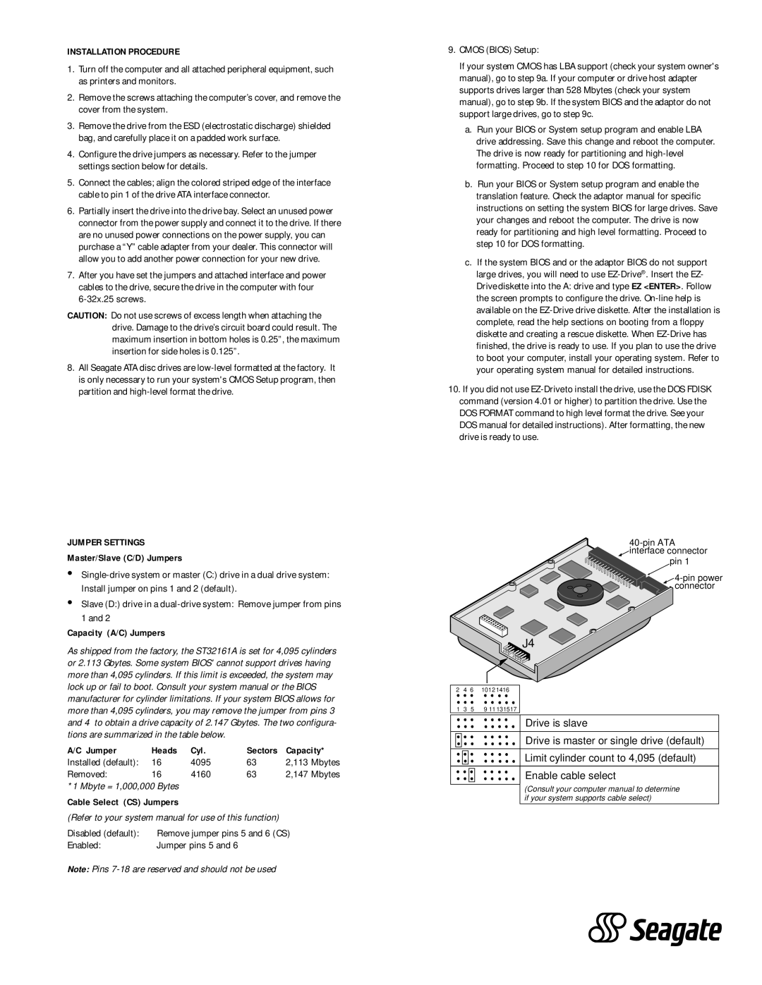
![]() interface connector
interface connector
pin 1
|
|
| J4 |
2 | 4 | 6 | 1012 1416 |
1 | 3 | 5 | 9 11 131517 |
|
|
| Drive is slave |
|
|
| Drive is master or single drive (default) |
|
|
| Limit cylinder count to 4,095 (default) |
|
|
| Enable cable select |
(Consult your computer manual to determine if your system supports cable select)
Note: Pins