Cheetah NS SAS
ST3400755SS
Page
Contents
Seagate Technology support services
Defect and error management
Installation
Interface requirements
List of Figures
Typical ST3400755SS drive +5V and +12V current profiles
Cheetah NS SAS Product Manual, Rev. B
Scope
Cheetah NS SAS Product Manual, Rev. B
Electromagnetic compatibility
Standards, compliance and reference documents
Standards
Electromagnetic susceptibility
Compliance
Reference documents
Cheetah NS SAS Product Manual, Rev. B
General description
Performance
Standard features
Media description
Reliability
Programmable drive capacity
Factory-installed options
Formatted capacities
ST3400755SS
Cheetah NS SAS Product Manual, Rev. B
Access time
Performance characteristics
Internal drive characteristics
Seek performance
Start/stop time
Format command execution time minutes
General performance characteristics
Caching write data
Prefetch/multi-segmented cache control
Cache operation
Prefetch operation
Recoverable Errors
Reliability specifications
Error rates
Unrecoverable Errors
Interface errors
Reliability and service
Seek errors
Preventive maintenance
Performance impact
4 S.M.A.R.T
Controlling S.M.A.R.T
Reporting control
Thermal monitor
Temperature Log Page 0Dh
Predictive failures
Implementation
State of the drive prior to testing
DST failure definition
Invoking DST
Extended test Function Code 010b
Product warranty
Short test Function Code 001b
Log page entries
Shipping
Product repair and return information
Cheetah NS SAS Product Manual, Rev. B
DC power requirements
Physical/electrical specifications
AC power requirements
ST3400755SS DC power requirements
Conducted noise immunity
General DC power requirement notes
Power sequencing
Current profiles
Power dissipation
Typical ST3400755SS drive +5V and +12V current profiles
Temperature
Environmental limits
Shock and vibration
Relative humidity
Effective altitude sea level
Shock
Package size Packaged/product weight Drop height
Recommended mounting
Acoustics
Air cleanliness
Vibration
Corrosive environment
X表示该部件(于同类物品程度上)所含的危险和有毒物质中国RoHS MCV标准所定义的门槛值。
China Restriction of Hazardous Substances RoHS Directive
Mechanical specifications
Physical dimensions
Cheetah NS SAS Product Manual, Rev. B
Drive error recovery procedures
Defect and error management
Drive internal defects/errors
77.87
Media Pre-Scan
SAS system errors
Background Media Scan
Deferred Auto-Reallocation
Idle Read After Write
Installation
Drive orientation
Cooling
Air flow
Drive mounting
Grounding
Cheetah NS SAS Product Manual, Rev. B
SAS features
Interface requirements
Dual port support
Command name Command code Supported
Scsi commands supported
Commands supported by Cheetah NS SAS family drives
Commands supported by Cheetah NS SAS family drives
Commands supported by Cheetah NS SAS family drives
Commands supported by Cheetah NS SAS family drives
Cheetah NS SAS inquiry data Bytes Data hex
Mode Sense data
Inquiry data
Page
2.1 ST3400755SS Mode Sense data
Mode Pages
Supported Feature or condition
Miscellaneous operating features and conditions
Miscellaneous features
Miscellaneous status
SAS physical interface
Datum B
Physical characteristics
Connector requirements
Pin descriptions
Pin Signal name Signal type
Electrical description
SAS pin descriptions
SAS transmitters and receivers
Signal characteristics
Power
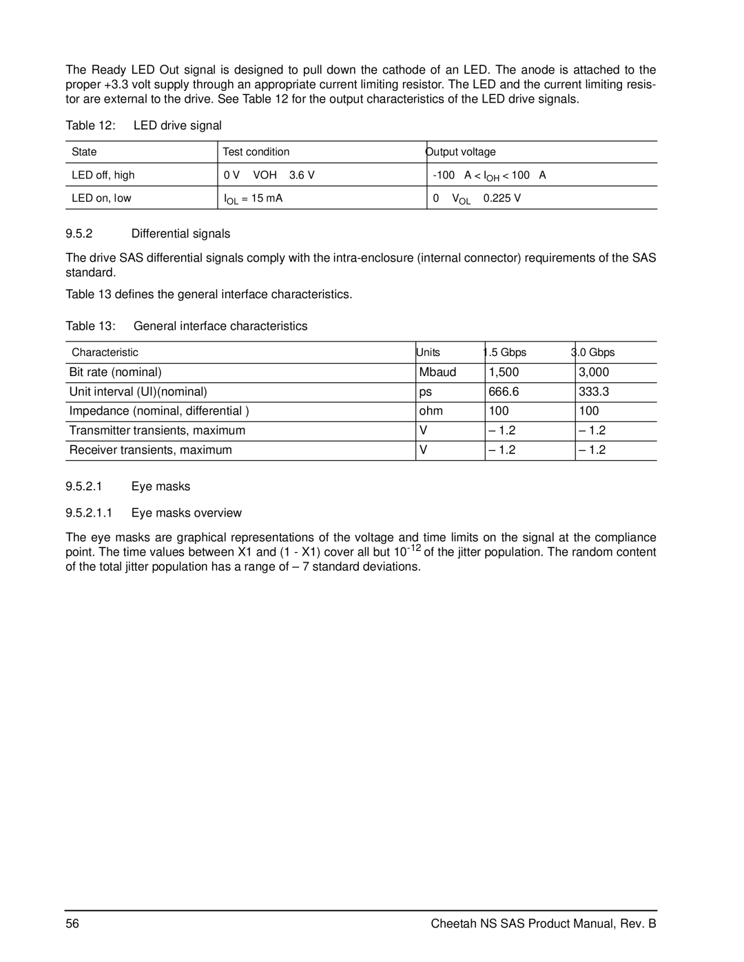
Ready LED Out
General interface characteristics
LED drive signal
Differential signals
Eye masks Eye masks overview
Absolute amplitude
Receive eye mask
Jitter tolerance masks
Normalized time in UI
Jitter
Peak-to
Sinusoidal
Frequency in kHz
Transmitter signal characteristics
Signal characteristica Units Gbps
Maximum allowable jitter
Receiver signal characteristics
Signal characteristic Units Gbps
Gbps m, n Deterministic jitterq
Compliant jitter test pattern Cjtpat
Impedance specifications
Receiver jitter tolerance
Impedance requirements Sheet 1
Electrical TxRx connections
Transmitter characteristics
Impedance requirements Sheet 2
= -5,437dB
Shows the zero-length test load
Receiver characteristics
Cheetah NS SAS Product Manual, Rev. B
Presales Support
Seagate Technology support services
Internet
Technical Support
Data Recovery Services Call Center Toll-free Direct dial
Warranty Service
Data Recovery Services Authorized Service Centers
Index
Numerics
Page
SAS
See also cooling