9.5.2.3.2Receiver jitter tolerance
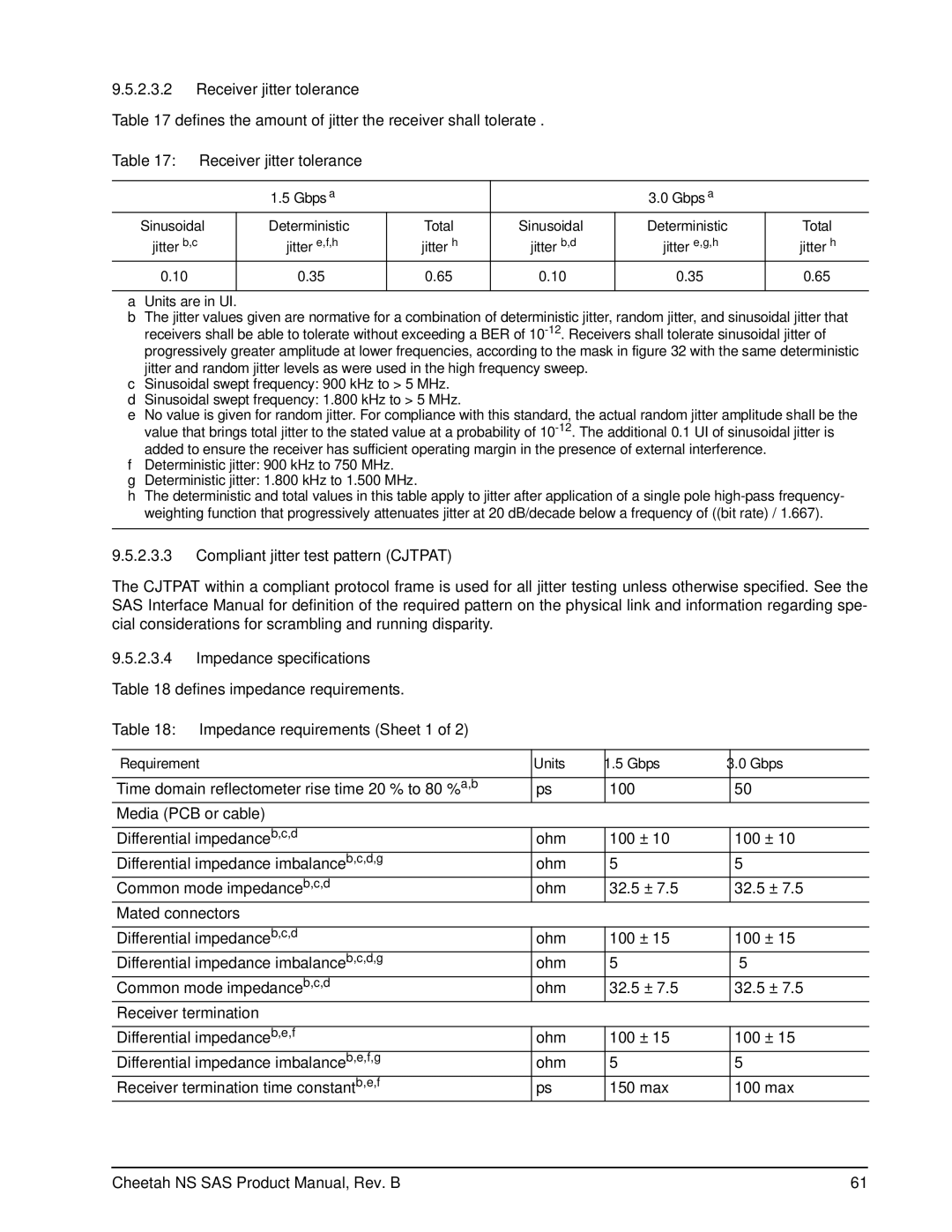
Table 17 defines the amount of jitter the receiver shall tolerate .
Table 17: Receiver jitter tolerance
| 1.5 Gbpsa |
|
| 3.0 Gbpsa |
|
Sinusoidal | Deterministic | Total | Sinusoidal | Deterministic | Total |
jitterb,c | jittere,f,h | jitterh | jitterb,d | jittere,g,h | jitterh |
0.10 | 0.35 | 0.65 | 0.10 | 0.35 | 0.65 |
|
|
|
|
|
|
aUnits are in UI.
bThe jitter values given are normative for a combination of deterministic jitter, random jitter, and sinusoidal jitter that receivers shall be able to tolerate without exceeding a BER of
cSinusoidal swept frequency: 900 kHz to > 5 MHz.
dSinusoidal swept frequency: 1.800 kHz to > 5 MHz.
eNo value is given for random jitter. For compliance with this standard, the actual random jitter amplitude shall be the value that brings total jitter to the stated value at a probability of
fDeterministic jitter: 900 kHz to 750 MHz.
gDeterministic jitter: 1.800 kHz to 1.500 MHz.
hThe deterministic and total values in this table apply to jitter after application of a single pole
9.5.2.3.3Compliant jitter test pattern (CJTPAT)
The CJTPAT within a compliant protocol frame is used for all jitter testing unless otherwise specified. See the SAS Interface Manual for definition of the required pattern on the physical link and information regarding spe- cial considerations for scrambling and running disparity.
9.5.2.3.4Impedance specifications
Table 18 defines impedance requirements.
Table 18: Impedance requirements (Sheet 1 of 2)
Requirement | Units | 1.5 Gbps | 3.0 Gbps |
|
|
|
|
Time domain reflectometer rise time 20 % to 80 %a,b | ps | 100 | 50 |
Media (PCB or cable) |
|
|
|
|
|
|
|
Differential impedanceb,c,d | ohm | 100 ± 10 | 100 ± 10 |
Differential impedance imbalanceb,c,d,g | ohm | 5 | 5 |
Common mode impedanceb,c,d | ohm | 32.5 ± 7.5 | 32.5 ± 7.5 |
Mated connectors |
|
|
|
|
|
|
|
Differential impedanceb,c,d | ohm | 100 ± 15 | 100 ± 15 |
Differential impedance imbalanceb,c,d,g | ohm | 5 | 5 |
Common mode impedanceb,c,d | ohm | 32.5 ± 7.5 | 32.5 ± 7.5 |
Receiver termination |
|
|
|
|
|
|
|
Differential impedanceb,e,f | ohm | 100 ± 15 | 100 ± 15 |
Differential impedance imbalanceb,e,f,g | ohm | 5 | 5 |
Receiver termination time constantb,e,f | ps | 150 max | 100 max |
Cheetah NS SAS Product Manual, Rev. B | 61 |