Barracuda 9LP Installation Guide, Rev. E | 39 |
[3]
C
[1]
E
![]() G
G
D
F
A
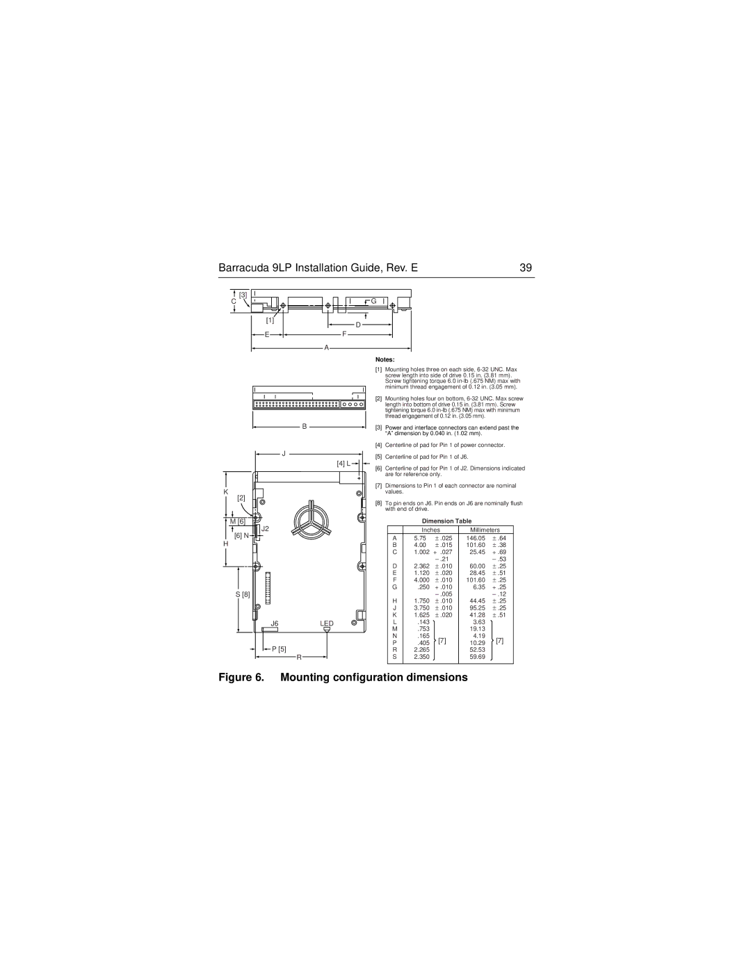
Notes:
| [1] | Mounting holes three on each side, |
|
| screw length into side of drive 0.15 in. (3.81 mm). |
|
| Screw tightening torque 6.0 |
|
| minimum thread engagement of 0.12 in. (3.05 mm). |
| [2] | Mounting holes four on bottom, |
|
| length into bottom of drive 0.15 in. (3.81 mm). Screw |
|
| tightening torque 6.0 |
|
| thread engagement of 0.12 in. (3.05 mm). |
B | [3] | Power and interface connectors can extend past the |
|
| “A” dimension by 0.040 in. (1.02 mm). |
| [4] | Centerline of pad for Pin 1 of power connector. |
J | [5] | Centerline of pad for Pin 1 of J6. |
| ||
| [4] L | Centerline of pad for Pin 1 of J2. Dimensions indicated |
| [6] | |
|
| are for reference only. |
K | [7] | Dimensions to Pin 1 of each connector are nominal |
| values. |
[2] | [8] | To pin ends on J6. Pin ends on J6 are nominally flush | ||||
| ||||||
|
| with end of drive. |
|
|
| |
M [6] |
|
| Dimension Table |
| ||
J2 |
|
| Inches | Millimeters | ||
[6] N |
| A | 5.75 | ± .025 | 146.05 | ± .64 |
H |
| |||||
| B | 4.00 | ± .015 | 101.60 | ± .38 | |
|
| C | 1.002 | + .027 | 25.45 | + .69 |
|
|
|
|
| ||
|
| D | 2.362 | ± .010 | 60.00 | ± .25 |
|
| E | 1.120 | ± .020 | 28.45 | ± .51 |
|
| F | 4.000 | ± .010 | 101.60 | ± .25 |
S [8] |
| G | .250 | + .010 | 6.35 | + .25 |
|
|
|
| |||
|
| H | 1.750 | ± .010 | 44.45 | ± .25 |
|
| J | 3.750 | ± .010 | 95.25 | ± .25 |
|
| K | 1.625 | ± .020 | 41.28 | ± .51 |
J6 | LED | L | .143 |
| 3.63 |
|
|
| M | .753 |
| 19.13 |
|
|
| N | .165 | [7] | 4.19 | [7] |
|
| P | .405 | 10.29 | ||
P [5] |
|
|
| |||
| R | 2.265 |
| 52.53 |
| |
| R | S | 2.350 |
| 59.69 |
|