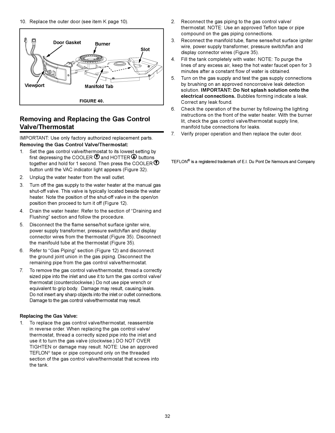
10. Replace the outer door (see item K page 10).

Door Gasket

Burner


Slot

Viewport

Manifold Tab

FIGURE 40.

Removing and Replacing the Gas Control Valve/Thermostat

IMPORTANT: Use only factory authorized replacement parts.

Removing the Gas Control Valve/Thermostat:

1.Set the gas control valve/thermostat to its lowest setting by first depressing the COOLER and HOTTER buttons together and hold for 1 second. Then press the COOLER button until the VAC indicator light appears (Figure 32).

2.Unplug the water heater from the wall outlet.

3.Turn off the gas supply to the water heater at the manual gas shut-off valve. This valve is typically located beside the water heater. Note the position of the shut-off valve in the open/on position then proceed to turn it off (Figure 12).

4.Drain the water heater. Refer to the section of “Draining and Flushing” section and follow the procedure.

5.Disconnect the the flame sense/hot surface igniter wire, power supply transformer, pressure switch/fan and display connector wires from the thermostat (Figure 35). Disconnect the manifould tube at the thermostat (Figure 35).

6.Refer to “Gas Piping” section (Figure 12) and disconnect the ground joint union in the gas piping. Disconnect the remaining pipe from the gas control valve/thermostat.

7.To remove the gas control valve/thermostat, thread a correctly sized pipe into the inlet and use it to turn the gas control valve/ thermostat (counterclockwise.) Do not use pipe wrench or equivalent to grip body. Damage may result, causing leaks. Do not insert any sharp objects into the inlet or outlet connections. Damage to the gas control valve/thermostat may result.

Replacing the Gas Valve:

1.To replace the gas control valve/thermostat, reassemble in reverse order. When replacing the gas control valve/ thermostat, thread a correctly sized pipe into the inlet and use it to turn the gas valve (clockwise.) DO NOT OVER TIGHTEN or damage may result. NOTE: Use an approved TEFLON® tape or pipe compound only on the threaded section of the gas control valve/thermostat that screws into the tank.

2.Reconnect the gas piping to the gas control valve/ thermostat. NOTE: Use an approved Teflon tape or pipe compound on the gas piping connections.

3.Reconnect the manifold tube, flame sense/hot surface igniter wire, power supply transformer, pressure switch/fan and display connector wires (Figure 35).

4.Fill the tank completely with water. NOTE: To purge the lines of any excess air, keep the hot water faucet open for 3 minutes after a constant flow of water is obtained.

5.Turn on the gas supply and test the gas supply connections by brushing on an approved noncorrosive leak detection solution. IMPORTANT: Do Not splash solution onto the electrical connections. Bubbles forming indicate a leak. Correct any leak found.

6.Check the operation of the burner by following the lighting instructions on the front of the water heater. With the burner lit, check the gas control valve/thermostat supply line, manifold tube connections for leaks.

7.Verify proper operation and then replace the outer door.

TEFLON® is a registered trademark of E.I. Du Pont De Nemours and Company

32

Page 32
Image 32
Sears 153.33262 manual Removing and Replacing the Gas Control Valve/Thermostat, Removing the Gas Control Valve/Thermostat

153.33262 specifications

Sears 153.33262 is a well-regarded electronic device in the field of household tools, specifically known as a versatile and reliable multi-function meter. Designed for both novice users and seasoned professionals, this meter is an essential instrument for a wide range of applications, including electrical diagnostics and home repair tasks.

One of the key features of the Sears 153.33262 is its capability to measure both AC and DC voltage, making it suitable for a variety of electrical projects. The device supports voltage measurements up to a specific range, allowing users to conduct thorough checks on outlets, circuits, and battery-powered systems. This versatility makes it an invaluable tool for electricians, technicians, and DIY enthusiasts alike.

In addition to voltage measurement, the Sears 153.33262 also boasts a multimeter functionality that includes current and resistance measurement capabilities. Users can easily measure current in different ranges, which is essential for assessing circuit loads and diagnosing electrical issues. The resistance measurement feature is beneficial for checking the integrity of wiring and components, ensuring that users can troubleshoot and resolve problems efficiently.

The design of the Sears 153.33262 emphasizes user-friendly operation. The meter typically incorporates a large, easy-to-read display that provides clear readings in various lighting conditions. The rotating selector switch allows users to switch between different measurement modes with ease, streamlining the workflow and minimizing the risk of errors.

This device is built with durability in mind, often featuring a rugged casing that can withstand the wear and tear associated with frequent use in various environments. Its portability is enhanced by its lightweight construction, allowing users to carry it easily to different job sites or locations within the home.

Furthermore, the Sears 153.33262 may also include features such as audible alerts for continuity testing, data hold functions, and battery-saving modes, further enhancing its functionality. The availability of probes and leads designed specifically for the meter ensures that users receive accurate measurements consistently.

In summary, the Sears 153.33262 is a multi-function electrical meter that stands out for its combination of versatility, user-friendly features, and robust construction. Whether one is performing simple checks around the house or engaged in complex electrical diagnostics, this meter serves as a reliable companion for all electrical measurement needs.