ASSEMBLYOF RECOVERY TANK
AND SOLUTION TANK
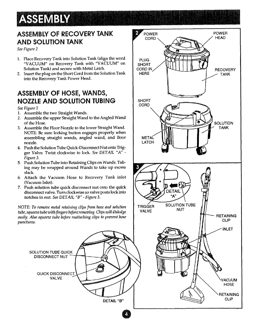
See Figure 2
1, Place Recovery Tal& into Solution Tank (align the word
"VACUUM" on Recovery Tank with "VACUUM" on Solution Tank) and secure with Metal Latch.
2, Insert the plug on the Short Cord from the Solution Tank into the Recovery Tank Power Head.
ASSEMBW OF HOSE, WANDS, NOZZLE AND SOLUTION TUBING
See Figure 1
1.Assemble the two Straight Wands.
2.Assemble the upper Straight Wand to the Angled Wand of the Hose.
3, Assemble the Floor Nozzle to the lower Straight Wand. NOTE: Be sure locking button engages properly when
assembling straight wands, angled wand, and floor nozzle,
4.Push the Solution Tube
5.Push Solution Tube into Retaining Clips on Wands. Tub-
ing may be wrapped around Wands to take up excess slack.
6.Attach the Vacuum Hose to Recovery Tank inlet (Vacuum halet).
7.Push solution tube quick disconnect nut onto the quick disconnect valve. Turn clockwise so valve posts lock into notches in nut. See DETAIL "B" - Figure 3.
NOTE: To remove metal retaining clips from hose and solution tube, squeeze tube with fingers before removing, Clips will dislodge easily. Also squeeze tube before reattaching clips to prevent hose
punctures.
SOLUTION TUBE QUICK
DISCONNECT NUT
QUICK DISCONNECT
VALVE
DETAIL "B"
O0wERPOWER
RDHEAD
PLUG |
|
SHORT |
|
CORD | RECOVERY |
HERE | TANK |
SHORT
CORD
\
TANK
LATCH
l
TRIGGER | SOLUTION TUBE | |
NUT | ||
VALVE | ||
|
RETAINING
CLIP
HOSE
lING
CLIP