i.i
ASSEMBLY
IF THIS UNIT IS RECEIVED
BLED, REVIEW ALL STEPS IN THIS
SECTION TO BE SURE ASSEMBLY
WARNING:
CORRECT AND
FORTHE OPERATOR.
HOW TO ASSEMBLE YOUR BRUSHWACKER
DANGER:
. Engineer,,/ ThrottleHandle
Screw_Retention
Mounting'//// Clip
8r cket /
Figure 2
SPARK ARRESTOR SCREEN ASSEMBLY (See Fig. 3 )
. | BARRIER | TO KEEP THE | OPERATOR'S | Your Brushwackeris shipped with a spark arrestor screen |
| ||||
..- | FEETFROMB:Ir_._BITHEBLADE- | _: '.acc_scry. fyouplantouseyourBrushwaskerinanarea |
| ||||||
- |
| . | .......... |
| Whe'ma spark arrestor muffler is required by local state, or |
| |||
.....HANDLEBAR | ASSEMBLY | (See | Fig. 1 ) " | " federal | authorities (See =Special Notice" on page 4), pro- |
| |||
.............. |
|
|
|
|
| ceed to nsta | as fo owe. |
| |
uerore installing me | " | ......... |
| ||||||
• thumbscrew |
| securing the mounting brackets to the Outer | • •.Loosen 4 screws rmm c_lnaer cover wJtnnex Key. | • | |||||
housing, |
|
|
|
|
| move cylinder cover. |
| ||
Refer to Figure 15 for proper handlebar Position.
•Place the hand/ebarbetween the upperand lower brack-
eL The mounting bracket shouldbe between the arrows on the handlebar. Secure with thumb screw.
•We recommend you adjust the angle of the handlebarfor best comfort and balance after the unit is assembled.
Figure1
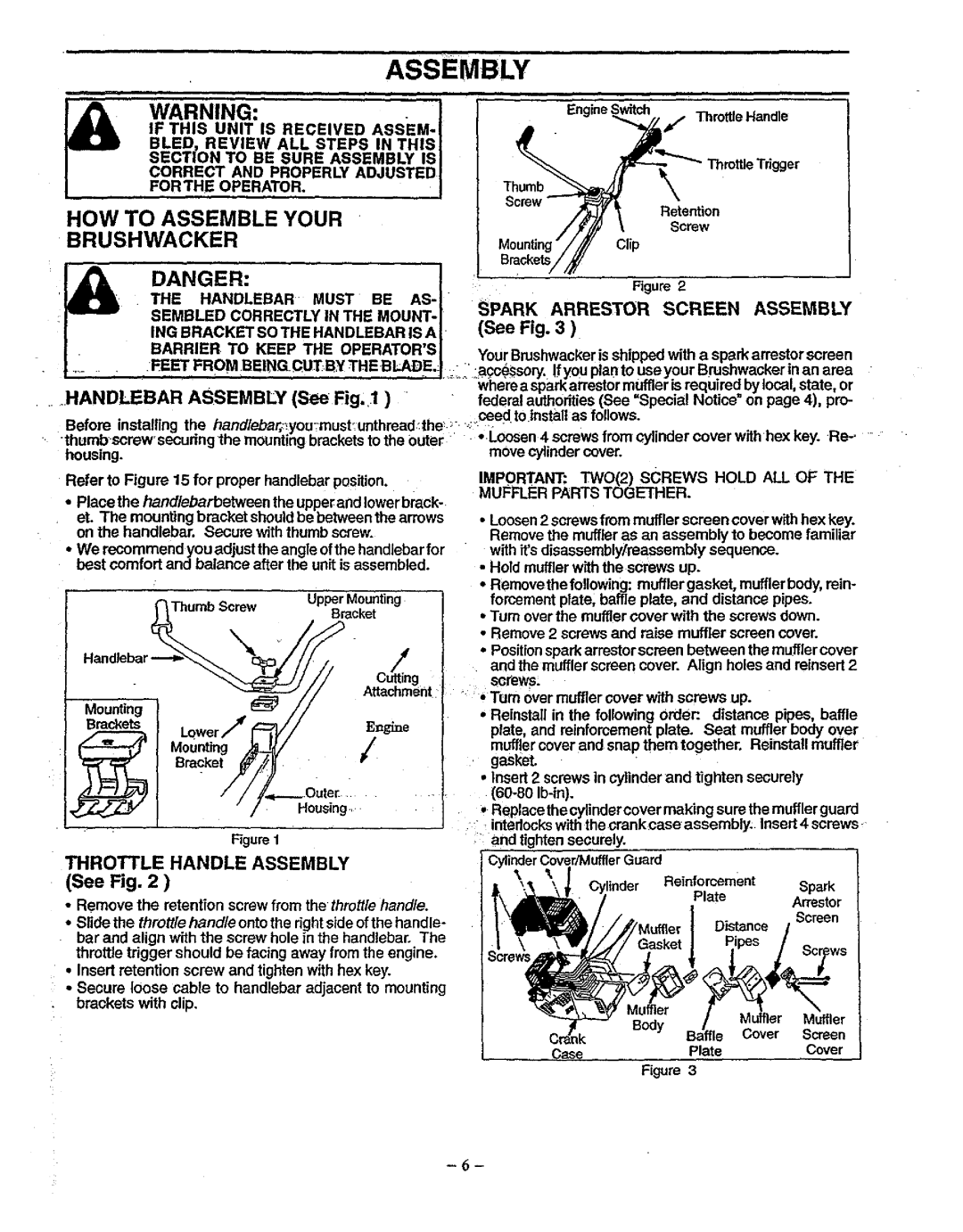
THROTTLE HANDLE ASSEMBLY (See Fig. 2 )
•Remove the retention screw from the thrott/e hand/e.
•Slide the thrott/e hand/e onto the rightside of the handle- bar and align with the screw hole in the handlebar. The throttle trigger should be facing away from the engine.
•Insert retention screw and tighten with hex key.
•Secure loose cable to handlebar adjacent to mounting brackets with dip.
IMPORTANT: TWO(2) sCREWS HOLD ALL OF THE MUFFLER PARTS TOGETHER.
•Loosen 2 screws from muffler screen cover with hex key. Remove the muffler as an assembly to become familiar with it'sdisassembly/reassembly sequence.
•Hold muffler with the screws up.
•Removethe fo!lowing: muffler gasket, mufflerbody, rein- forcement plate; baffle plate, and distance pipes.
•Turn over the muffler cover with the screws down.
•Remove 2 screws and raise muffler screen cover.
•Positionspark arrestor screen between the muffler cover and the muffler screen cover. Align holes and reinsert 2 8cl_ev_s_
"' * Turn over muffler cover with screws up.
•Reinstall in the following Order:. distance pipes, baffle plate and reinforcement plate. Seat muffler body over
muffler cover and snap them together. Reinstall muffler gasket.
•Insert 2 screws in cylinder and tighten securely
•Replacethe cylindercover making sure the mufflerguard interlockswith the crank case assembly. Insert 4 screws,
•and tighten securely.
CylinderCover/MufflerGuard
Reinforcement Spark
_X".'_ _\;. Cylinder PlateArrestor
Screen
Muffler Distance /
Muffler Muffler
CrankB_ Cover Screen
CasePlateCover
Figure 3