| GENERAL | INFORMATION |
|
|
|
| ||
| Table h Pump Performance Chart (In Gallons Per Minute) |
|
|
| ||||
|
|
|
| Discharge |
|
|
|
|
Pump |
| Suction | Discharge | Pressure | Pumping Depth in Feet |
| ||
Model | Description | Size | Size | P.S.I. | 5' | 10' | 15' | 20' |
390.2508 | 1/2 HP Standard S.W. Jet | 3/4" | 40 | 7.3 | 6.2 | 5.2 | 4.2 | |
MAJOR COMPONENTS AND
WHAT THEY DO
| Relief |
| Valve |
| ie Tee |
Water System | and Priming Plug |
| |
| Check |
| Valve |
23140E96
Figure I
Impeller and Jet
Impeller turns with motor shaft, causing the water to fly out from its rim by centrifugal force. Impeller rotation creates a vacuum which puUs in more water. Part of the water is di- verted back to the jet where it passes through the nozzle and venturi. This creates more vacuum to draw in more water.
In shallow wells (less than 20 feet deep), the vacuum cre-
ated at the pump is enough to pull water to the pump.
Therefore, for shallow well use the jet is built into the pump.
PIPING
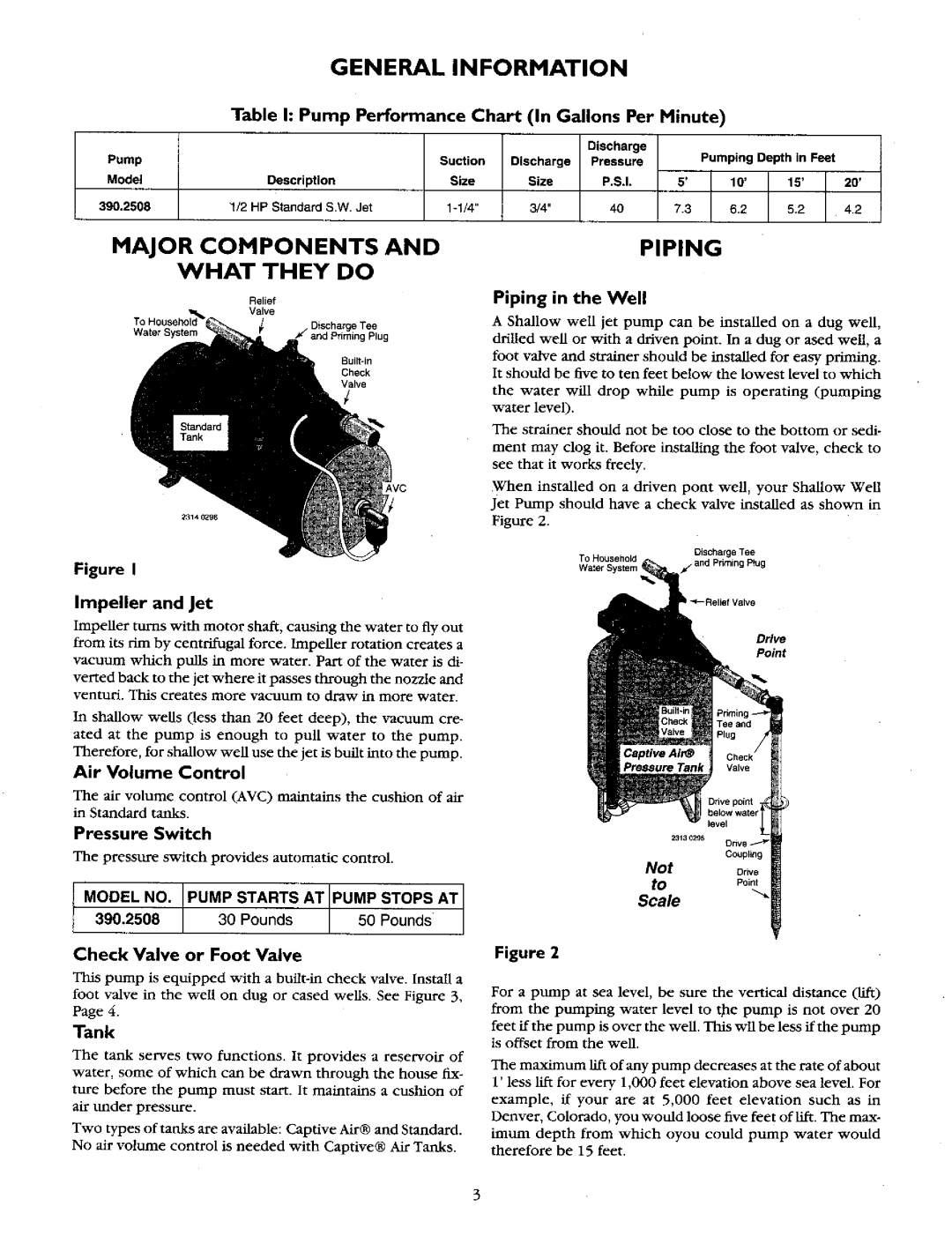
Piping in the Well
A Shallow well jet pump can be installed on a dug well, drilled well or with a driven point. In a dug or ased well, a foot valve and strainer should be installed for easy priming. It should be five to ten feet below the lowest level to which
the water will drop while pump is operating (pumping water level).
The strainer should not be too close to the bottom or sedi- ment may clog it. Before installing the foot valve, check to see that it works freely.
When installed on a driven pont well, your Shallow Well Jet Pump should have a check valve installed as shown in
Figure 2.
To Household | Discharge Tee |
Water System | f- and Priming Plug |
II
Drive
Point
Air Volume Control
The air volume control (AVC) maintains the cushion of air in Standard tanks.
Pressure Switch
The pressure switch provides automatic control.
MODEL NO. PUMP STARTS AT [PUMP STOPS AT
390.2508 | _ | / _ |
Check Valve or Foot Valve
This pump is equipped with a
foot valve in the well on dug or cased wells. See Figure 3, Page 4.
Tank
The tank serves two functions. It provides a reservoir of water, some of which can be drawn through the house fix-
ture before the pump must start. It maintains a cushion of air under pressure.
Two types of tanks are available: Captive Air® and Standard.
No air vohtme control is needed with Captive® Air Tanks.
Couplin9
NotOrive
toPoint
Scale
Figure 2
For a pump at sea level, be sure the vertical distance (lift) from the pumping water level to the pump is not over 20
feet if the pump is over the well. This wll be less if the pump is offset from the well.
The maximum lift of any pump decreases at the rate of about 1' less lifx for every 1,000 feet elevation above sea level. For
example, if your are at 5,000 feet elevation such as in Denver, Colorado, you would loose five feet of llfx. The max- imum depth from which oyou could pump water would
therefore be 15 feet.