ELECTRICAL
WIRING CONNECTIONS
,AWARNING] Fire hazard. Incorrect voltage can cause a fire or seriously damage the motor and voids the warranty. The supply voltage must be within + 10% of the motor name- plate voltage.
NOTICE:
volts. If necessary, reconnect the motor for 115 volts, as shown. Do not alter the wiring in single voltage motors.
Install, ground, wire, and maintain your pump in compli-
ance with 'the National Electrical Code (NEC) or the
Canadian Electrical Code (CEC), as applicable, and with all
local codes and ordinances that apply. Consult your local
building inspector for code information.
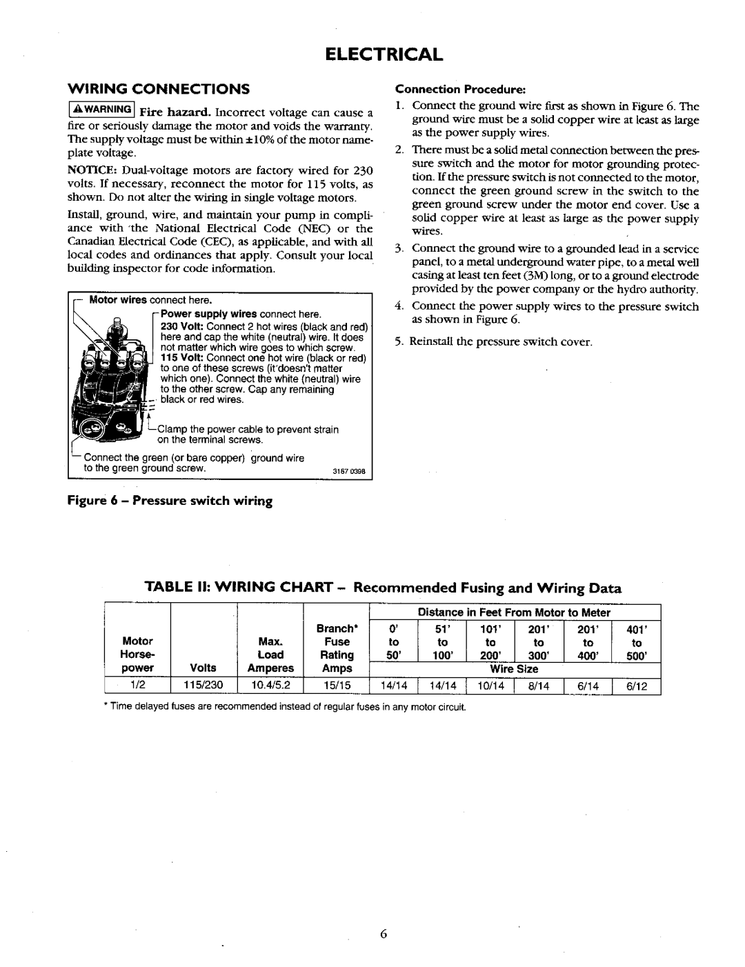
Motor wires connect here.
-Power supply wires connect here.
230Volt: Connect 2 hot wires (black and red) here and cap the white (neutral) wire. It does not matter which wire goes to which screw
115Volt: Connect one hot wire (black or red) to one of these screws (it'doesn'tmatter which one). Connect the white (neutral) wire
to the other screw. Cap any remaining black or red wires,
prevent | strain |
on the terminal screws. |
|
green (or bare copper) ground wire |
|
to the green ground screw. | 31870398 |
Connection Procedure:
1.Connect the ground wire first as shown in Figure 6. The ground wire must be a solid copper wire at least as large as the power supply wires.
2.There must be a solid metal connection between the pres-
sure switch and the motor for motor grounding protec-
tion. If the pressure switch is not connected to the motor,
connect the green ground screw in the switch to the green ground screw under the motor end cover. Use a
solid copper wire at least as large as the power supply wires.
. Connect the ground wire to a grounded lead in a service
panel, to a metal underground water pipe, to a metal well casing at least ten feet (3M) long, or to a ground electrode
provided by the power company or the hydro authority.
4.Connect the power supply wires to the pressure switch as shown in Figure 6.
5.Reinstall the pressure switch cover.
Figure 6 - Pressure switch wiring
TABLE Ih WIRING CHART - Recommended Fusing and Wiring Data
|
|
|
|
| Distance in Feet From Motor to Meter |
| |||
|
|
| Branch* | 0' | 51' | 101' | 201' | 201' | 401' |
Motor |
| Max. | Fuse | to | to | to | to | to | to |
Horse- |
| Load | Rating | 50' | 100' | 200' | 300' | 400' | 500' |
power | Volts | Amperes | Amps |
|
| Wire Size |
|
| |
1/2 | 115/230 | 10.4/5.2 | 15/15 | 14/14 | r 14/14 | { 10/14! | 8/t416/1416/12 |
| |
• Time delayed fuses are recommended instead of regular fuses in any motor circuit.
6