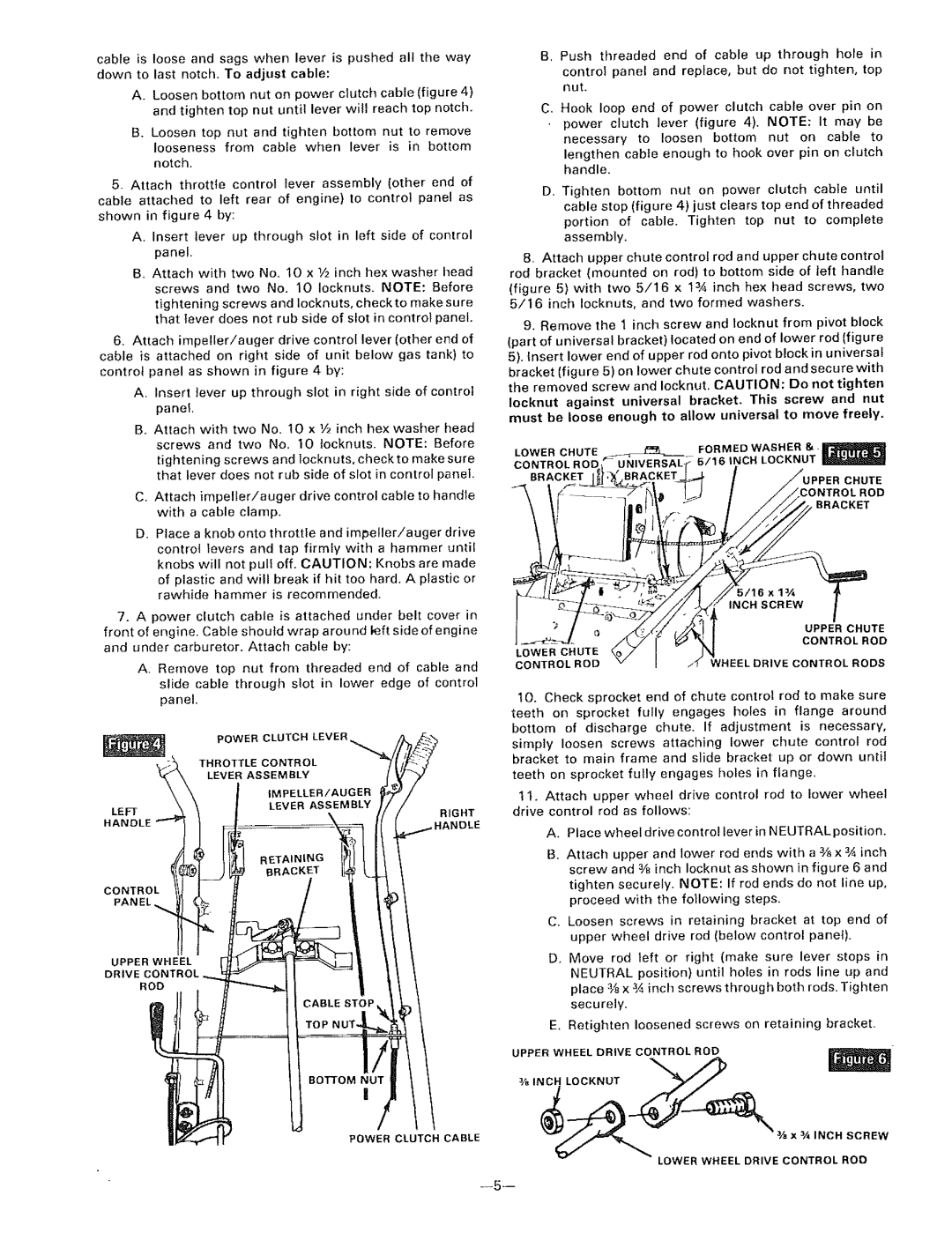
cable is loose and sags when lever is pushed all the way down to last notch. To adjust cable:

A. Loosen bottom nut on power clutch cable (figure 4) and tighten top nut until lever will reach top notch.

B. Loosen top nut and tighten bottom nut to remove

looseness from cable when lever is in bottom notch.

5_ Attach throttte control lever assembly (other end of cable attached to left rear of engine} to control panel as shown in figure 4 by:

A. Insert lever up through slot in left side of control panel.

B. Attach with two No. 10 x 1/2 inch hex washer t_ead screws and two No. 10 Iocknuts. NOTE: Before

tightening screws and locknuts, check to make sure that lever does not rub side of slot in control panel.

6.Attach impeller!auger drive control lever (other end of cable is attached on right side of unit below gas tank) to controt panel as shown in figure 4 by:

A.Insert lever up through slot in right side of control panel

B.Attach with two No. 10 x 1/2 inch hex washer head screws and two No. 10 {ocknuts. NOTE: Before tightening screws and ]ocknuts, check to make sure that lever does not rub side of slot in control panel.

C.Attach impeller/auger drive control cable to handle with a cable clamp.

D.Place a knob onto throttle and impeller/auger drive controi tevers and tap firmly with a hammer until

knobs will not pull off. CAUTION: Knobs are made of plastic and will break if hit too hard. A plastic or rawhide hammer is recommended.

7.A power clutch cabte is attached under belt cover in front of engine. Cable shoutd wrap around left side of engine

and under carburetor. Attach cable by:

A.Remove top nut from threaded end of cable and slide cable through slot in lower edge of control panel.

B. Push threaded end of cable up through hole in

control panel and replace, but do not tighten, top nut.

C, Hook loop end of power clutch cable over pin on power clutch lever (figure 4). NOTE: It may be

necessary to loosen bottom nut on cable to lengthen cable enough to hook over pin on clutch handle.

D. Tighten bottom nut on power clutch cabEe until cable stop (figure 4) just clears top end of threaded

portion of cable. Tighten top nut to complete assembly.

8.Attach upper chute control rod and upper chute control rod bracket (mounted on rod) to bottom side of left handle (figure 5) with two 5/16 x 13/4 inch hex head screws, two 5/16 inch Iocknuts, and two formed washers.

9.Remove the 1 inch screw and locknut from pivot block

(part of universal bracket) located on end of lower rod (figure 5). insert lower end of upper rod onto pivot block in universal bracket (figure 5) on lower chute control rod and securewith

the removed screw and Iocknut. CAUTION: Do not tighten

Iocknut against universal bracket. This screw and nut must be loose enough to allow universal to move freely.

FORMED WASHER 8,. _jl_._

LOWER CHUTE _._._5/16 INCH LOCKNUT

CONTROL ROD

BRACKET

BRACKET _

CHUTE

BRACKET


5/16x1¾


INCH

SCREW


UPPER

CHUTE

LOWER CHUTE


CONTROL ROD


CONTROL ROD

WHEEL

DRIVE CONTROL

RODS

10.Check sprocket end of chute control rod to make sure

teeth on sprocket fully engages holes in flange around

bottom of discharge chute. If adjustment is necessary,

simply loosen screws attaching lower chute control rod bracket to main frame and sIide bracket up or down until

teeth on sprocket fully engages holes in flange.

1 I. Attach upper wheel drive control rod to lower wheel drive control rod as follows:

A. Place wheel drive control lever in NEUTRALposition.

B. Attach upper and lower rod ends with a _ x 3,4inch screw and 3/8inch Iocknut as shown in figure 6 and

tighten securely. NOTE: If rod ends do not line up, proceed with the following steps.

C. Loosen screws in retaining bracket at top end of upper wheel drive rod (below control panel).

D. Move rod left or right (make sure lever stops in NEUTRAL position) until holes in rods line up and place 3,_x 3,4inch screws through both rods. Tighten securely.

E. Retighten loosened screws on retaining bracket.

UPPER WHEEL DRIVE CONTROL ROD

3/S _NCH LOCKNUT_

-- ox ,NcNsc

LOWER WHEEL DRIVE CONTROL ROD

--5 m

Page 5
Image 5
Sears 536.9183 owner manual Ox ,NcNsc

536.9183 specifications

The Sears 536.9183 is a versatile and reliable snow blower designed to tackle winter's toughest challenges. This machine is particularly noted for its robust build quality and user-friendly operation, making it an ideal choice for homeowners dealing with heavy snowfall.

One of the standout features of the Sears 536.9183 is its powerful engine. Equipped with a dependable gas-powered motor, it delivers ample horsepower that enables the snow blower to easily clear driveways, sidewalks, and patios. This engine is designed for efficient performance, proving to be fuel-efficient while still offering the torque necessary to navigate through dense snow and ice.

In terms of design, the 536.9183 showcases a well-thought-out structure that ensures durability and ease of use. It features a heavy-duty auger system made of steel, capable of breaking through hard-packed snow and ice. The auger effectively collects the snow and propels it through the chute, allowing for a clean and thorough clearing process. Additionally, the adjustable chute provides the flexibility to direct the snow away from the areas that have already been cleared, minimizing the effort needed to maintain a clear path.

The snow blower offers multiple speed settings, allowing users to navigate various conditions with ease. Whether tackling light, fluffy snow or heavier, compacted snow, the adjustable speed settings provide tailored performance. Moreover, the self-propelled function ensures that users can maneuver the machine effortlessly, reducing physical strain during operation.

Safety features are also a priority in the design of the Sears 536.9183. It comes equipped with user-friendly controls that are easy to understand and operate, ensuring that even novice users can handle the machine effectively. Additionally, the snow blower includes safety measures such as an emergency shut-off and a protective shield around the auger and impeller to prevent accidents.

In summary, the Sears 536.9183 stands out in the realm of snow blowers due to its powerful engine, durable construction, and thoughtful safety features. Its combination of efficiency, ease of use, and performance make it an excellent choice for homeowners looking to tackle winter's snow with confidence. As winter approaches, having the Sears 536.9183 ready to go ensures that homeowners can keep their pathways clear and safe throughout the season.