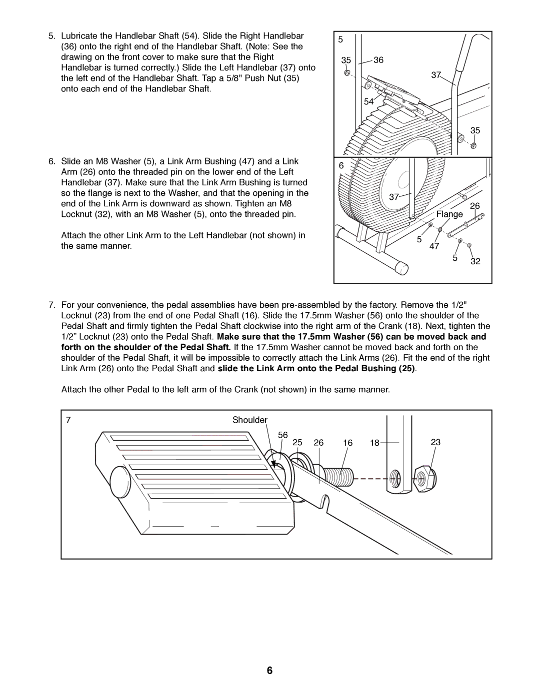
5.Lubricate the Handlebar Shaft (54). Slide the Right Handlebar (36) onto the right end of the Handlebar Shaft. (Note: See the drawing on the front cover to make sure that the Right Handlebar is turned correctly.) Slide the Left Handlebar (37) onto the left end of the Handlebar Shaft. Tap a 5/8" Push Nut (35) onto each end of the Handlebar Shaft.
6.Slide an M8 Washer (5), a Link Arm Bushing (47) and a Link Arm (26) onto the threaded pin on the lower end of the Left Handlebar (37). Make sure that the Link Arm Bushing is turned so the flange is next to the Washer, and that the opening in the end of the Link Arm is downward as shown. Tighten an M8 Locknut (32), with an M8 Washer (5), onto the threaded pin.
Attach the other Link Arm to the Left Handlebar (not shown) in the same manner.
5 |
|
|
35 | 36 |
|
| 37 |
|
| 54 |
|
|
| 35 |
6 |
|
|
| 37 | 26 |
| Flange | |
|
| |
| 5 |
|
| 47 |
|
| 5 | 32 |
|
|
7.For your convenience, the pedal assemblies have been
Attach the other Pedal to the left arm of the Crank (not shown) in the same manner.
7 | Shoulder |
|
|
|
|
| 56 | 26 | 16 | 18 | 23 |
| 25 |
6
