SERVHCE AND ADJUSTMENTS
TO REPLACE MOWER BLADE DRIVE BELT (See Fig. 23)
WITH PARKING BRAKE "ENGAGED"
The mower'blade drive belt may be replaced without tools,. Park the tractor on level su_ace,_ Engage parking brake._
BELT REMOVAL-
•Remove mower from tractor (See "TO REMOVE MOWER" in this section of this manual),
•Work belt off both mandrel pulleys and idler pulleys. = Pull belt away from mower,,
BELT INSTALLATION -
•Install new belt in reverse order of removal.
. | Make su re belt is in all pulley grooves and inside a!l belt |
| guides° |
. | install mower in reverse order of removal instructions |
MANDRELIDLER
PULLEYPULLEYS
MANDREL
PULLEY
FIG. 23
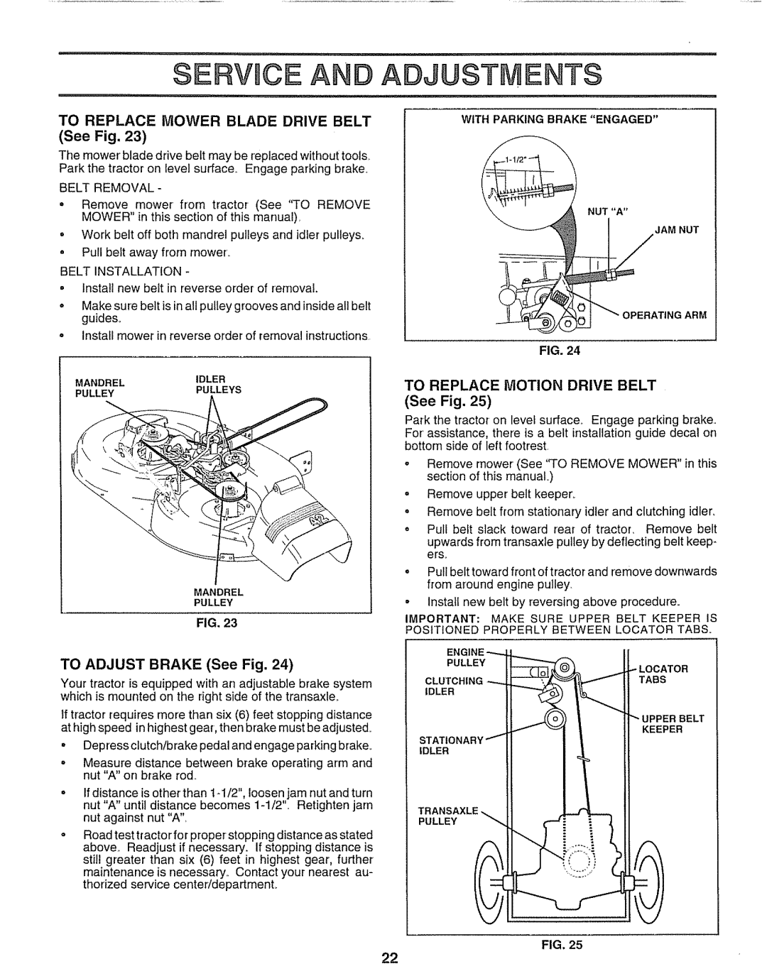
TO ADJUST BRAKE (See Fig. 24)
Your tractor is equipped with an adjustable brake system which is mounted on the right side of the transaxle_
tf tractor requires more than six (6) feet stopping distance at high speed in highest
°Depress clutch/brake pedal and engage parking brake.
. Measure distance between brake operating arm and nut "A" on brake rod,,
If distance is other than
Road test tractor for proper stopping distance as stated above. Readjust if necessary. If stopping distance is still greater than six (6) feet in highest gear, further maintenance is necessary. Contact your nearest au- thorized service center/department_
FIG. 24
TO REPLACE MOTION DRIVE BELT
(See Fig. 25)
Park the tractor on levei surface,, Engage parking brake,,
For'assistance, there is a belt installation guide decal on bottom side of left footrest.
oRemove mower (See "TO REMOVE MOWER" in this section of this manuaL)
°Remove upper belt keeper,.
=Remove belt from stationary idler and clutching idler, o Pull heft slack toward rear of tractor, Remove belt
upwards from transaxle pulley by deflecting belt keep- ers,,
oPull belt toward front of tractor and remove downwards from around engine pu]ley_
°instatt new belt by reversing above procedure.
IMPORTANT: MAKE SURE UPPER BELT KEEPER IS POSITIONED PROPERLY BETWEEN LOCATOR TABS.
ENG
PULLEY
LOCATOR
CLUTCHINGTABS IDLER
UPPER BELT
KEEPER
IDLER
TRANSAXLE
PULLEY
FIG. 25
22