SERVICE AN ADJUSTMENTS
J J,J IHLH,,J | Ill I I ill |
TO ADJUST MOTION CONTROL LEVER (See Fig. 29)
The motion control lever has been preset at the factory and adjustment should not be necessary_
If for any reason the motion control lever wil! not hold its position while at a selected speed, it may be adjusted at the friction pack located on the right side of transmission_
°Park tractor on tevel surface. Stop tractor by turning ignition key to "OFF" position, and engage parking brake.
. Adjust motion control lever by tightening adjustment tocknut one half (1/2) turn,
NOTE: If for any reason the effort to move the motion control lever becomes too excessive, reverse the above adjustment procedure by loosening Iocknut 1/4 to 1/2 turn.
Road test tractor after adjustment and repeat procedure if necessary.
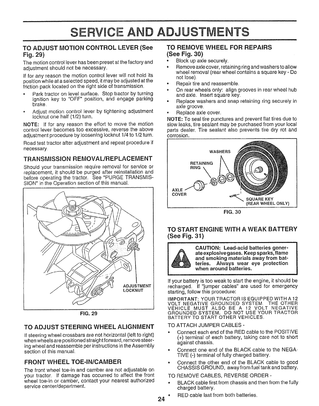
TO REMOVE WHEEL FOR REPAIRS
(See Fig. 30)
. Block up axle securely.
=Remove axle cover, retaining ring and washers to allow wheel removal (rear wheel contains a square key - Do not lose).
o Repair tire and reassemble.
oOn rear'wheels only: align grooves in rear wheel hub and axle,. Insert square key_
. Replace washers and snap retaining ring securely in axle groove.
. Replace axle cover,
NOTE: To seal tire punctures and prevent flat tires due to slow leaks, tire sealant may be purchased from your local
parts dealer. Tire sealant also prevents tire dry rot and corrosion,
WASHERS
TRANSMISSION REMOVAIJREPLACEMENT
Should your transmission require removal for service or replacement, it should be purged after reinstallation and before operating the tractor. See "PURGE TRANSMIS- SION" in the Operation section of this manual
RETAINING RING
AXLE
COVER
t
SQUARE KEY
(REAR WHEEL ONLY)
FIG. 30
ADJUSTMENT
LOCKNUT
FIG. 29
TO ADJUST STEERING WHEEL ALIGNMENT
If steering wheel crossbars are net horizontal (left to right) when wheels are positioned straight forward, remove steer-
ing wheel and reassemble per instructions in the Assembly section of this manual
FRONT WHEEL TOE-IN/CAMBER
The front wheel
TO START ENGINE WITH A WEAK BATTERY (See Fig, 31)
iii iii
CAUTION:
and smoking materials away from bat- teries. Always wear eye protection when around batteries.
If your battery is too weak to start the engine, it should be
recharged. If "jumper' cables" are used for emergency starting, follow this procedure:
IMPORTANT: YOUR TRACTOR IS EQUIPPED WITH A 12
VOLT NEGATIVE GROUNDED SYSTEM THE OTHER
VEHICLE MUST ALSO BE A 12 VOLT NEGATIVE GROUNDED SYSTEM. DO NOT USE YOUR TRACTOR BATTERY TO START OTHER VEHICLES.
TO ATTACH JUMPER CABLES -
-Connect each end of the RED cable to the POSITIVE
(+)terminal of each battery, taking care not to short against chassis.
•Connect one end of the BLACK cable to the NEGA - TIVE
°Connect the other end of the BLACK cable to good CHASStS GROUND, away from fuel tank and battery,
TO REMOVE CABLES, REVERSE ORDER
oBLACK cable first from chassis and then from the fully charged battery.
o RED cable last from both batteries.
24