This manual should remain with the unit
Models 04758-2 6 kW NG, 7 kW LP 04759-2 12 kW NG, 12 kW LP
04760-2 13 kW NG, 15 kW LP
Not intended for use as Primary Power in place of utility
‹ HOW TO OBTAIN SERVICE
‹ CONTENTS
‹ OPERATION AND MAINTENANCE
INTRODUCTION
Section 4 - Maintenance
Section 2 - Post Installation Start-up
and Adjustments
Section 5 - Troubleshooting
WARNING
GENERAL HAZARDS
IMPORTANT SAFETY INSTRUCTIONS
This product contains or emits chemicals
EXPLOSION HAZARDS
ELECTRICAL HAZARDS
FIRE HAZARDS
‹ STANDARDS INDEX
1.3 SYSTEM SET LED
1.1 UNPACKING/INSPECTION
1.2 PROTECTION SYSTEMS
DANGER
Figure 1.2 - 12 kW/15 kW, V-twin GT-990/760 Engine
1.4 THE GENERATOR
Figure 1.1 - 7 kW, Single Cylinder GH-410 Engine
‹ 1.5.2 ENGINE
1.5 SPECIFICATIONS
‹ 1.5.1 GENERATOR
1.7 FUEL CONSUMPTION
1.8 RECONFIGURING THE FUEL SYSTEM
1.6 FUEL REQUIREMENTS AND RECOMMENDATIONS
DANGER
‹ 1.9.1 GENERATOR
1.9 LOCATION
‹ 1.8.2 12KW AND 15KW, 990CC ENGINES
Figure 1.4 - Demand Regulator
‹ 1.9.2 TRANSFER SWITCH 1.9.2.1 7 kW, 12 kW and 15 kW Units
1.10 BATTERY INSTALLATION
1.11 THE BATTERY
Figure 1.5 - Battery Cable Connections
2.3 ELECTRICAL CHECKS
2.2 CHECK TRANSFER SWITCH OPERATION
2.1 BEFORE INITIAL START-UP
Section 2 - Post Installation Start-up and Adjustments
2.4 GENERATOR TESTS UNDER LOAD
2.5 CHECKING AUTOMATIC OPERATION
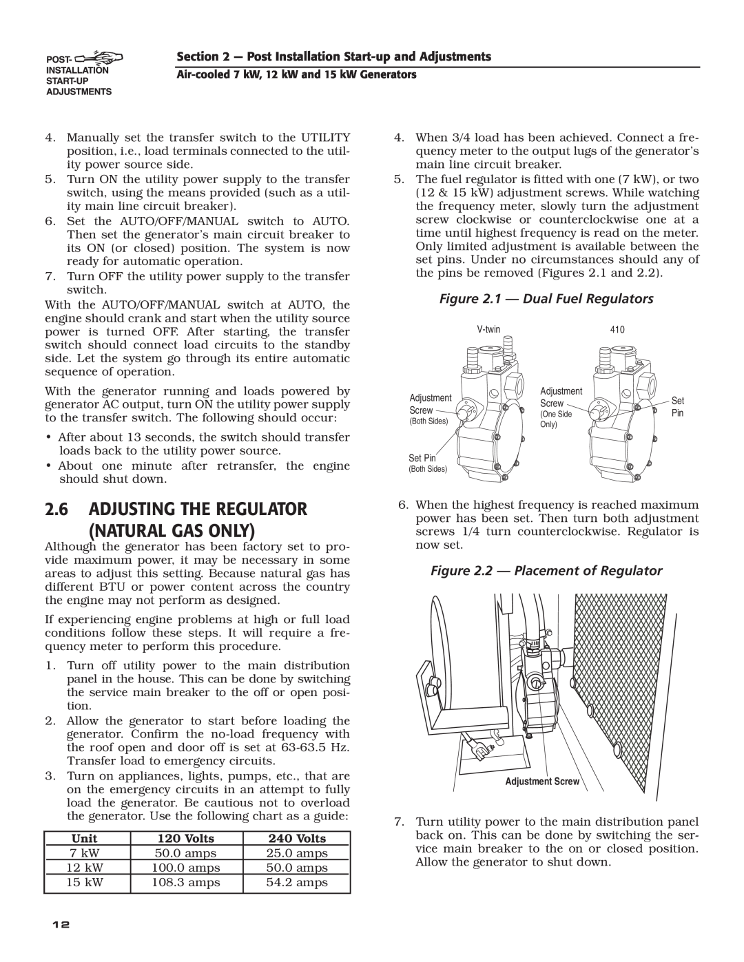
Figure 2.1 - Dual Fuel Regulators
2.6 ADJUSTING THE REGULATOR NATURAL GAS ONLY
Figure 2.2 - Placement of Regulator
Figure 2.4 - V-twin Engine Governor Adjustment
2.7 ENGINE GOVERNOR ADJUSTMENT
Figure 2.3 - Single Cylinder Engine Governor Adjustment
Figure 2.5 - V-twin Full Load Speed Adjust Screw
Figure 2.6 - Voltage Adjustment Potentiometer
2.8 VOLTAGE REGULATOR ADJUSTMENT
3.1 BREAK-IN PROCEDURE
‹ 3.2.1 “AUTO” POSITION
3.5 MANUAL TRANSFER OPERATION
3.3 AUTOMATIC TRANSFER OPERATION
3.4 SEQUENCE OF AUTOMATIC OPERATION
‹ 3.5.1 TRANSFER TO GENERATOR POWER SOURCE
‹ 3.7.1 LOW OIL PRESSURE SWITCH
3.6 SETTING THE EXERCISE TIMER
‹ 3.5.2 TRANSFER BACK TO UTILITY POWER SOURCE
Figure 3.2 - Manual Transfer Switch Operation
4.1 FUSE
‹ 3.7.2 HIGH TEMPERATURE SWITCH
Figure 3.3 - Low Oil Pressure and High Temperature Switches
4.2 CHECKING THE ENGINE OIL LEVEL
4.3 CHANGING THE ENGINE OIL
4.5 CHANGING THE ENGINE AIR CLEANER
‹ 4.3.2 OIL CHANGE PROCEDURE
4.4 CHANGING THE OIL FILTER
Figure 4.7 - 12 kW and 15 kW Engine Air Cleaner
4.7 BATTERY MAINTENANCE
Figure 4.6 - 7 kW, Engine Air Cleaner Location
Figure 4.8 - Setting the Spark Plug Gap
4.9 COOLING SYSTEM
4.8 ADJUSTING VALVE CLEARANCE
Figure 4.10 - Valve Clearance Adjustment
‹ 4.12.2 RETURN TO SERVICE
4.12 OUT OF SERVICE PROCEDURE
‹ 4.12.1 REMOVAL FROM SERVICE
4.10 ATTENTION AFTER SUBMERSION
be performed by the nearest Authorized Dealer
4.13 SERVICE SCHEDULE
ATTENTION It is recommended that all service work
Cause
5.1 TROUBLESHOOTING GUIDE
Problem
Correction
ENGINE WIRING
Section 6 - Electrical Data
CONNECTION
CONTROL PANEL BOX
CUSTOMER
Electrical Schematic - 12 & 15 kW - Drawing No. 0D8501-B
Section 6 - Electrical Data
ENGINE WIRING
Section 6 - Electrical Data
CUSTOMER
225A
224A
Electrical Schematic - 7 kW - Drawing No. 0D9014-C
Section 7 - Exploded Views and Parts Lists
PRE PACKAGED UNITS ONLY
FOAM, EXHAUST SIDE ENCLOSURE FRONT
PART NO. QTY. DESCRIPTION
CLOTH, HARDWARE 266.7mm x 146mm 7KW
FOAM, BACK EXHAUST ENCLOSURE COVER
Section 7 - Exploded Views and Parts Lists
PART NO. QTY
DESCRIPTION
69 16A, 16B, 17
Views and Parts Lists
66 2, 5, 19, 20, 39, 40, 47, 64, 93 67 8, 11, 12 68 4, 5
72 27, 28 73 3, 32, 33, 34, 35, 36, 40
ITEM PART NO. QTY. DESCRIPTION
ASSEMBLY, CRANKCASE HOUSING WITH
ASSEMBLY, CRANKSHAFT HORIZONTAL
ROLLER BEARING, GOVERNOR PLATE
Section 7 - Exploded Views and Parts Lists
ASSY, IGNITION COIL GV-990 CYLINDER
7 kW Generator - Drawing No. 0D3504-E
1.8 FT
1.25 FT
12 kW and 15 kW Generator - Drawing No. 0D3417-L
32 31
1.44 FT
2.6 FT
3 FT
Section 7 - Exploded Views and Parts Lists
Section 7 - Exploded Views and Parts Lists
DESCRIPTION
Section 7 - Exploded Views and Parts Lists
Section 7 - Exploded Views and Parts Lists
DESCRIPTION
Section 7 - Exploded Views and Parts Lists
Section 7 - Exploded Views and Parts Lists
Drawing No
ALL DIMENSIONS IN MILLIMETERS INCHES
Section 8 - Mounting
Air-cooled
Section 9 - Notes
PURCHASER’S/OWNER’S WARRANTY RESPONSIBILITIES
YOUR WARRANTY RIGHTS AND OBLIGATIONS
MANUFACTURER’S EMISSION CONTROL SYSTEM WARRANTY COVERAGE
CALIFORNIA AND FEDERAL EMISSION CONTROL WARRANTY STATEMENT
EMISSION CONTROL SYSTEM WARRANTY
EMISSION RELATED PARTS INCLUDE THE FOLLOWING
THIS WARRANTY SHALL NOT APPLY TO THE FOLLOWING
GENERAC POWER SYSTEMS TWO YEAR LIMITED WARRANTY FOR GUARDIAN
WARRANTY SCHEDULE
PREPACKAGED EMERGENCY AUTOMATIC STANDBY GENERATORS