'ASSEMBLY INSTRUCTIONS CONTINUED
IMPORTANT
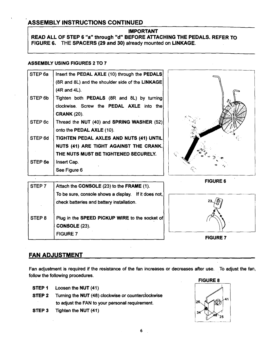
READ ALL OF STEP 6 "a" through "d" BEFORE ATTACHING THE PEDALS. REFER TO
FIGURE 6. THE SPACERS (29 and 30) already mounted on LINKAGE.
ASSEMBLY
STEP 6a
i STEP 6b
STEP 6c
STEP 6d
STEP 6e
USING FIGURES 2 TO 7
Insert the PEDAL AXLE (10) through the PEDALS 8R and 8L) and the shoulder side of the LINKAGE
(4R and 4L).
Tighten both PEDALS (SR and 8L) by turning clockwise. Screw the PEDAL AXLE into the
CRANK (20).
Thread the NUT (40) and SPRING WASHER (52) onto the PEDAL AXLE (10).
TIGHTEN PEDAL AXLES AND NUTS (4t) UNTIL
NUTS (4t) ARE TIGHT AGAINST THE CRANK,
THE NUTS MUST BE TIGHTENED SECURELY.
Insert Cap,
See Figure 6
STEP7
STEP8
FIGURE 6
Attach the CONSOLE (23) to the FRAME (1).
To be sure, console shows a display, if it does not, check batteries and battery installation.
Plug in the SPEED PICKUP WIRE to the socket ot
CONSOLE (23).
FIGURE 7
FIGURE 7
FAN ADJUSTMENT
Fan adjustment is required if the resistance of the fan increases or decreases after use. To adjust the fan,
follow the following procedures.
FIGURE 8
STEP1
STEP2
STEP 3
Loosen the NUT (41)
Tuming the NUT (48) clockwise or counterclockwise
to adjust the FAN to your personal requirement.Z6_41 Tighten the NUT (41)
6