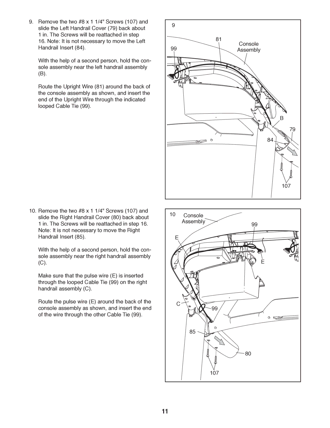
9. | Remove the two #8 x 1 1/4" Screws (107) and | 9 |
|
|
|
| slide the Left Handrail Cover (79) back about |
|
|
| |
| 1 in. The Screws will be reattached in step |
|
| 81 |
|
| 16. Note: It is not necessary to move the Left |
|
| Console | |
| Handrail Insert (84). | 99 |
|
| |
|
|
| Assembly | ||
| With the help of a second person, hold the con- |
|
|
|
|
| sole assembly near the left handrail assembly |
|
|
|
|
| (B). |
|
|
|
|
| Route the Upright Wire (81) around the back of |
|
|
|
|
| the console assembly as shown, and insert the |
|
|
|
|
| end of the Upright Wire through the indicated |
|
|
|
|
| looped Cable Tie (99). |
|
|
|
|
|
|
|
|
| B |
|
|
|
|
| 79 |
|
|
|
|
| 84 |
|
|
|
|
| 107 |
10. | Remove the two #8 x 1 1/4" Screws (107) and | 10 | Console |
|
|
| slide the Right Handrail Cover (80) back about |
|
| ||
| 1 in. The Screws will be reattached in step 16. |
| Assembly |
| 99 |
| Note: It is not necessary to move the Right |
|
|
|
|
| Handrail Insert (85). | E |
|
|
|
| With the help of a second person, hold the con- |
|
|
|
|
| sole assembly near the right handrail assembly |
|
|
| E |
| (C). |
|
|
| |
| Make sure that the pulse wire (E) is inserted |
|
|
|
|
| through the looped Cable Tie (99) on the right |
|
|
|
|
| handrail assembly (C). |
|
|
|
|
| Route the pulse wire (E) around the back of the | C |
|
|
|
| console assembly as shown, and insert the end |
| 99 |
| |
|
|
|
| ||
| of the wire through the other Cable Tie (99). |
|
|
|
|
|
|
| 85 |
|
|
|
|
|
|
| 80 |
|
|
|
| 107 |
|
|
| 11 |
|
|
|