ELECTROMAGNETIC LOCK Installation Manual
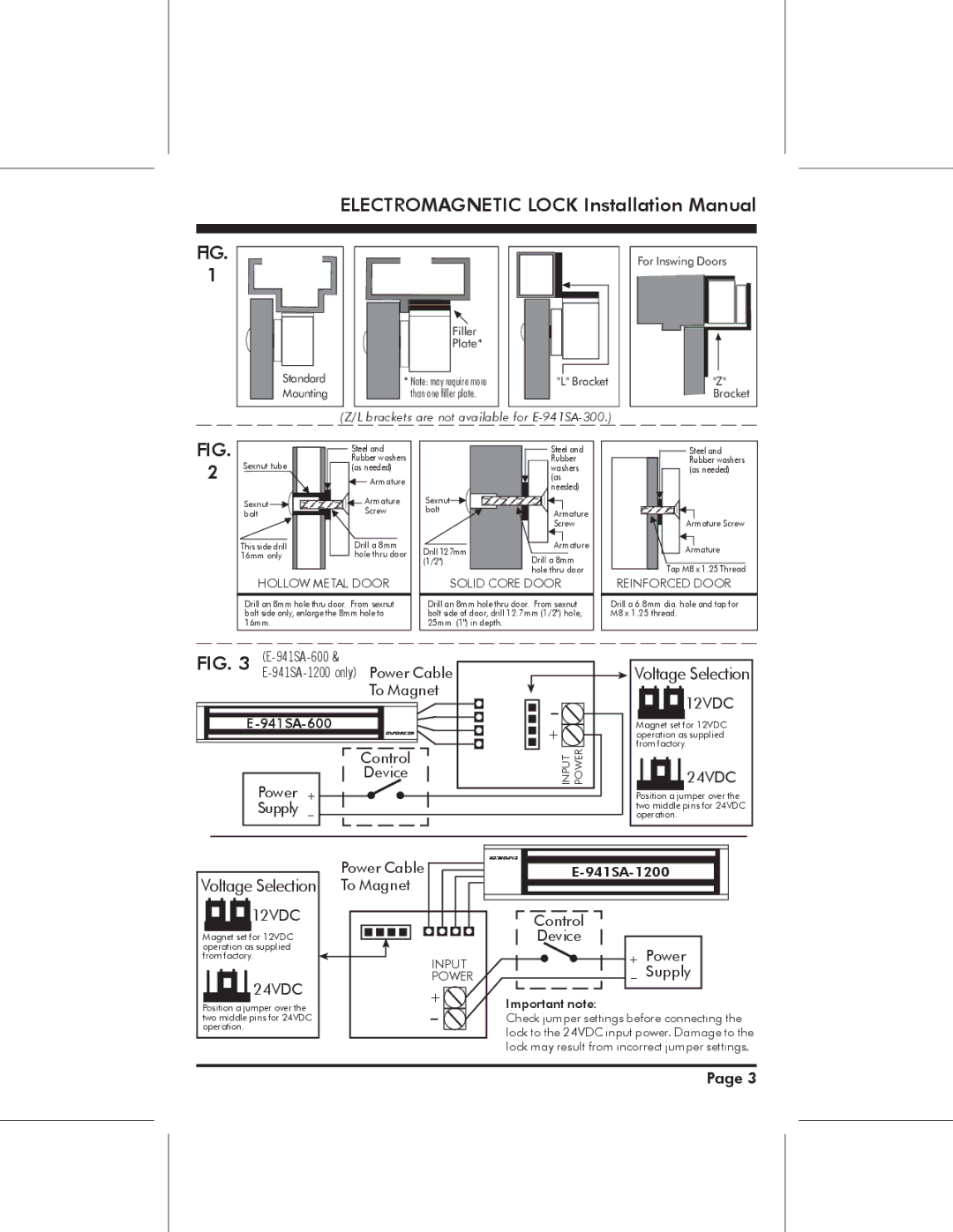
FIG.
1
Standard Mounting
Filler
Plate*
*Note: may require more than one filler plate.
"L" Bracket |
For Inswing Doors |
"Z" |
Bracket |
(Z/L brackets are not available for E-941SA-300.)
FIG.
2
Sexnut tube
Sexnut ![]()
![]() bolt
bolt ![]()
![]()
This side drill 16mm only
Steel and Rubber washers (as needed)
Armature
Armature
Screw
Drill a 8mm hole thru door
| Steel and | |
| Rubber | |
| washers | |
| (as | |
| needed) | |
Sexnut |
| |
bolt | Armature | |
| Screw | |
Drill 12.7mm | Armature | |
Drill a 8mm | ||
(1/2") | ||
| hole thru door |
Steel and Rubber washers (as needed)
Armature Screw
Armature
Tap M8 x 1.25 Thread
HOLLOW METAL DOOR
Drill an 8mm hole thru door. From sexnut bolt side only, enlarge the 8mm hole to 16mm.
SOLID CORE DOOR
Drill an 8mm hole thru door. From sexnut bolt side of door, drill 12.7mm (1/2") hole, 25mm (1") in depth.
REINFORCED DOOR
Drill a 6.8mm dia. hole and tap for M8 x 1.25 thread.
FIG. 3 | |
| |
| To Magnet |
ENFORCER
Control
Device
Power + ![]()
![]()
Supply -
- + ![]()
POWER
INPUT
 Voltage Selection
![]()
![]()
![]() 12VDC
12VDC
Magnet set for 12VDC operation as supplied from factory.
![]() 24VDC
24VDC
Position a jumper over the two middle pins for 24VDC operation.
Voltage Selection
![]()
![]()
![]() 12VDC
12VDC
Magnet set for 12VDC operation as supplied from factory.
![]() 24VDC
24VDC
Position a jumper over the two middle pins for 24VDC operation.
Power Cable ![]() To Magnet
To Magnet ![]()
INPUT POWER
+ ![]()
- ![]()
ENFORCER
Control |
|
Device |
|
+ | Power |
- | Supply |
Important note:
Check jumper settings before connecting the lock to the 24VDC input power. Damage to the lock may result from incorrect jumper settings.
Page 3