Magnetic Gate Lock Bracket Installation Manual
C. Mount the armature —
1.Once the electromagnet is mounted, determine the armature bracket location and tack weld into place. (Tack weld only.)
2.Dismount the armature plate from the bracket. Warning: Failure to remove the armature plate from the bracket will damage the armature and rubber washer. Weld the armature bracket with 3 or 4 beads about 1” apart. Make sure not to weld near the set screw hole. (See mounting diagram for “No Weld” areas.)
3.Remount the armature.
a.Put one rubber washer between two steel washers, and place them over the armature screw between the armature and the bracket. This will allow the armature to pivot slightly around the armature screw in order to compensate for gate misalignment.
b.Make sure the guide pins are inserted into guide holes to prevent the armature from spinning.
c.Do not overly tighten the armature against the bracket. The armature must be able to pivot around the armature screw.
D.Run the wires — The goal is to keep as little of the wires exposed as possible.
1.Run the wires into an
2.Use standard armored cable to prevent the wires from being cut between the electromagnet and the
E.Connect the wires: Note: Unit is prewired for 12V operation. See Wiring Diagram below for more information.
1.For 12V operation — Connect the red and white wires to +12VDC, and the black and green wires to ground.
2.For 24V operation — Connect the red wire to +24VDC, the green wire to ground, and then tie the white and black
wires together and insulate.
IMPORTANT: Damage caused by improper connection will void warranty.
F.Test the unit.
G.Insert the tamper caps into the mounting screw access holes of the electromagnet. This should be the last step, as once the tamper caps are in place, they are difficult to remove.
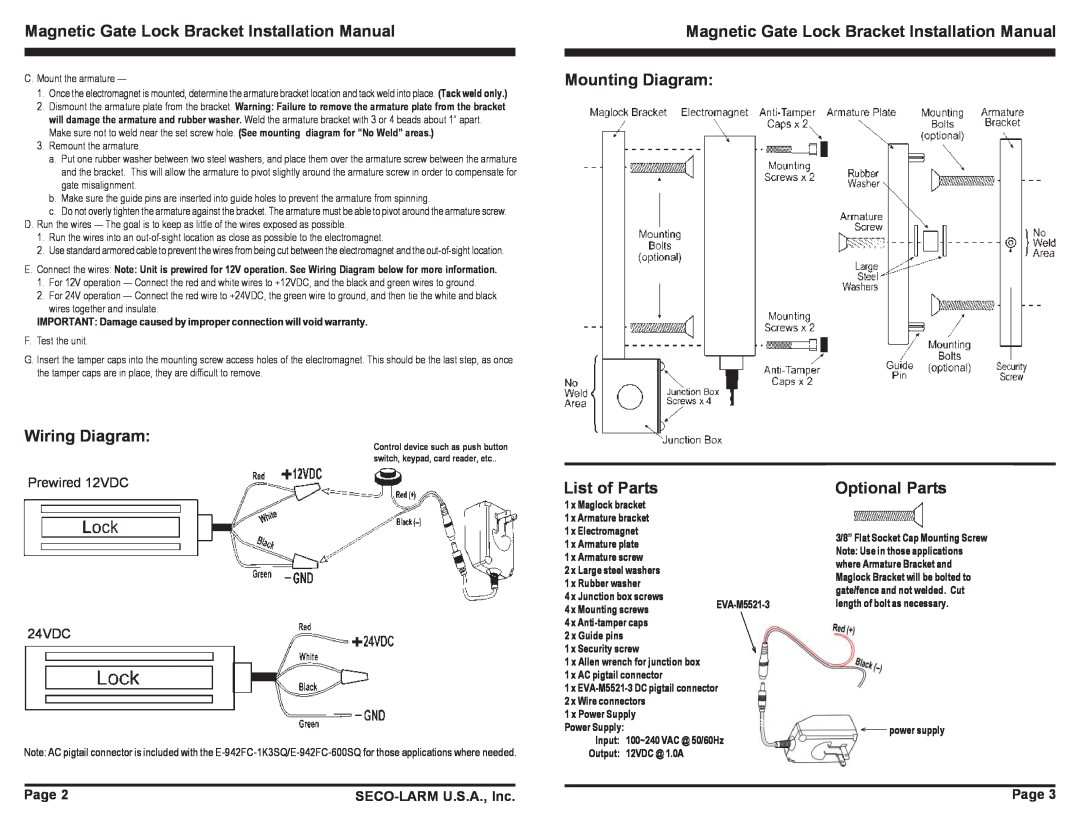
Magnetic Gate Lock Bracket Installation Manual Mounting Diagram:
Wiring Diagram:
Prewired 12VDC
24VDC
Control device such as push button switch, keypad, card reader, etc..
List of Parts
1 x Maglock bracket |
| |
1 x Armature bracket |
| |
1 x Electromagnet |
| |
1 x Armature plate |
| |
1 x Armature screw |
| |
2 x Large steel washers |
| |
1 x Rubber washer |
| |
4 x Junction box screws | ||
4 x Mounting screws | ||
|
4 x |
2 x Guide pins |
1 x Security screw |
1 x Allen wrench for junction box |
1 x AC pigtail connector |
1 x |
2 x Wire connectors |
1 x Power Supply |
Power Supply: |
Input: 100~240 VAC @ 50/60Hz |
Optional Parts
3/8” Flat Socket Cap Mounting Screw Note: Use in those applications where Armature Bracket and Maglock Bracket will be bolted to gate/fence and not welded. Cut length of bolt as necessary.
![]() power supply
power supply
Note: AC pigtail connector is included with the
Output: 12VDC @ 1.0A |
Page 2 |
| Page 3 |
|