9. Venting Cont.
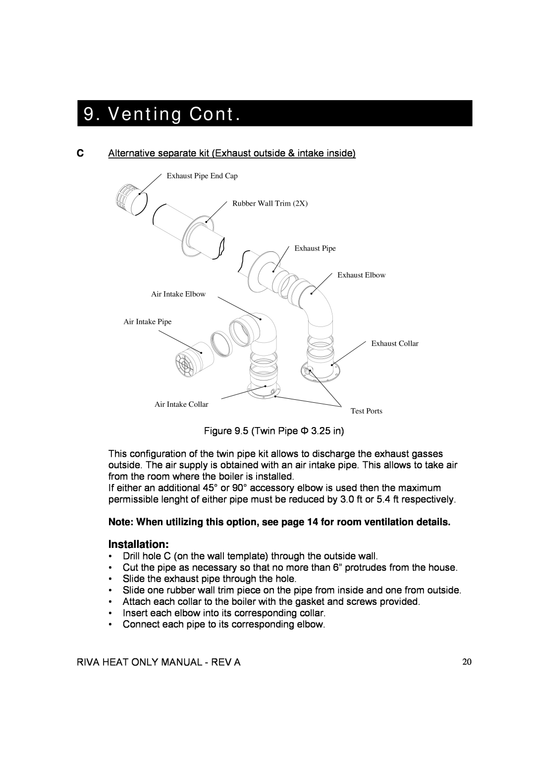
CAlternative separate kit (Exhaust outside & intake inside)
![]() Exhaust Pipe End Cap
Exhaust Pipe End Cap
Rubber Wall Trim (2X)
Exhaust Pipe
Exhaust Elbow
Air Intake Elbow
Air Intake Pipe
Air Intake Collar
Exhaust Collar
Test Ports
Figure 9.5 (Twin Pipe Φ 3.25 in)
This configuration of the twin pipe kit allows to discharge the exhaust gasses outside. The air supply is obtained with an air intake pipe. This allows to take air from the room where the boiler is installed.
If either an additional 45° or 90° accessory elbow is used then the maximum permissible lenght of either pipe must be reduced by 3.0 ft or 5.4 ft respectively.
Note: When utilizing this option, see page 14 for room ventilation details.
Installation:
•Drill hole C (on the wall template) through the outside wall.
•Cut the pipe as necessary so that no more than 6” protrudes from the house.
•Slide the exhaust pipe through the hole.
•Slide one rubber wall trim piece on the pipe from inside and one from outside.
•Attach each collar to the boiler with the gasket and screws provided.
•Insert each elbow into its corresponding collar.
•Connect each pipe to its corresponding elbow.
RIVA HEAT ONLY MANUAL - REV A | 20 |
