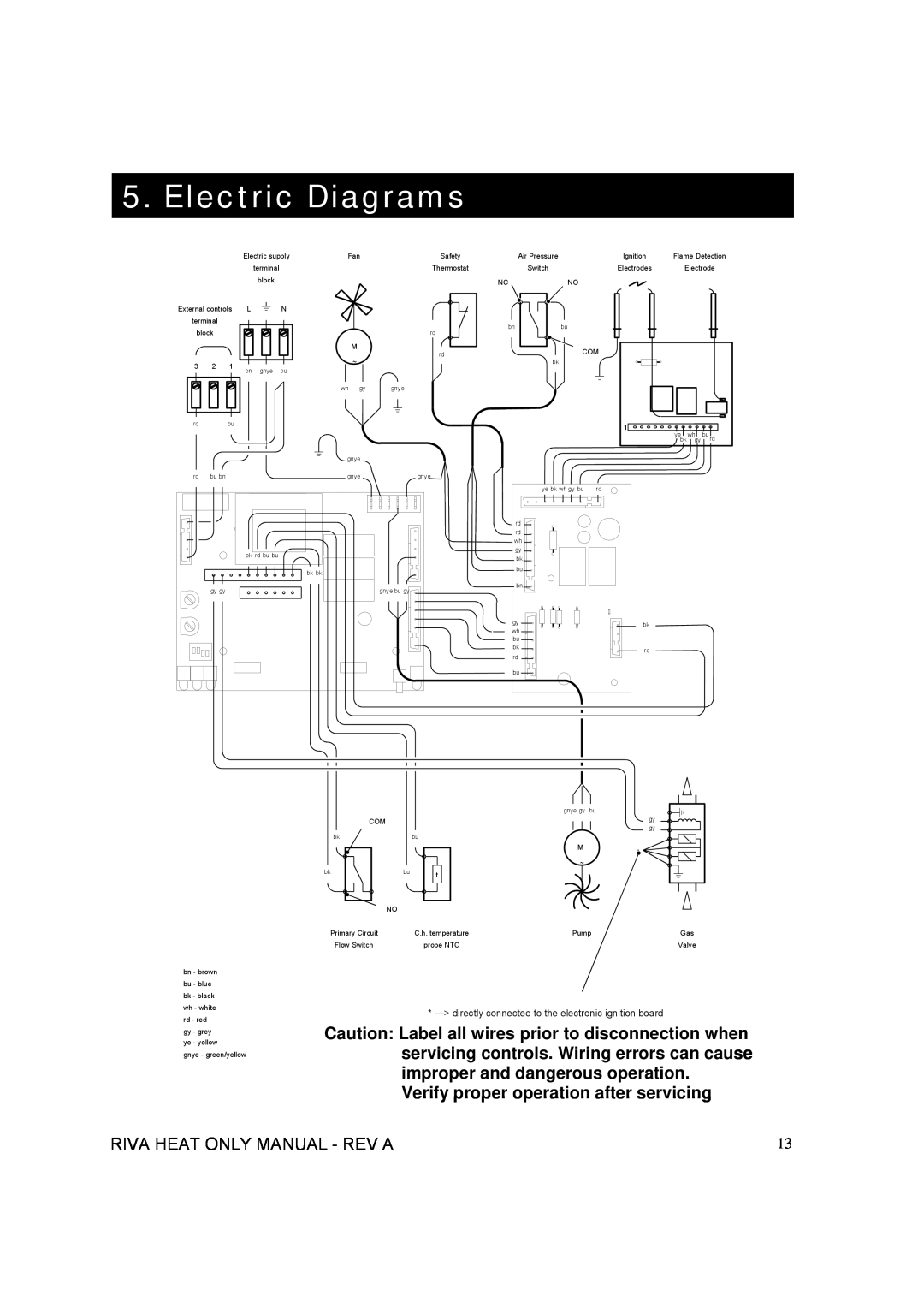
5. Electric Diagrams
Electric supply | Fan | Safety | Air Pressure | Ignition | Flame Detection |
|
| terminal |
|
| block |
External controls | L | N |
terminal |
|
|
block |
|
|
3 | 2 | 1 | bn | gnye | bu |
|
|
| |||
rd |
| bu |
|
|
|
|
| Thermostat |
|
| rd |
| M | rd |
| ~ | |
|
| |
wh | gy | gnye |
![]()
![]()
![]()
![]() gnye
gnye
| Switch |
NC | NO |
bn | bu |
| COM |
| bk |
Electrodes Electrode
1 |
yebk whgy bu rd |
rd | bu bn |
| bk rd bu bu |
bk bk
gy gy
gnye | gnye |
|
| ye bk wh gy bu | rd |
| rd |
|
| rd |
|
| wh |
|
| gy |
|
| bk |
|
| bu |
|
| bn |
|
| gnye bu gy |
|
| gy | bk |
| wh | |
|
| |
| bu |
|
| bk | rd |
| rd | |
|
| |
| bu |
|
COM |
bk |
bk |
bu
bu
t
gnye gy bu
M
~
gy |
gy |
* |
NO
bn - brown bu - blue bk - black wh - white rd - red gy - grey ye - yellow
gnye - green/yellow
Primary Circuit | C.h. temperature | Pump | Gas |
Flow Switch | probe NTC |
| Valve |
*
Caution: Label all wires prior to disconnection when servicing controls. Wiring errors can cause improper and dangerous operation.
Verify proper operation after servicing
RIVA HEAT ONLY MANUAL - REV A | 13 |