❏Installation Hardware (For Installation)
No. | Item | Diagram Qty. |
q Trim Plate | 1 | |
|
| <YFC054C088ZA> |
w Mounting Collar | 1 | |
|
| <YFX214C437ZA> |
e Lock Cancel Plate | 2 | |
|
| <YFX994C134ZA> |
r Mounting Bolt (5 mmø) | 1 | |
t | Tapping Screw | 1 |
| (5 mmø x 16 mm) |
|
y Hex. Nut (5 mmø) | 1 | |
|
| <ZZBISVD7001A> |
u Rear Support Strap | 1 | |
|
| <YEFG044C002> |
i | Round Head Screw | 2 |
| (5 mmø x 8 mm) |
|
o | 6 | |
| (5 mmø x 8 mm) |
|
|
| <ZZBISVD6503> |
❏Installation Hardware (For Wiring)
No. | Item | Diagram Qty. |
!0 | Power Connector | 1 |
| (ISO connector) |
|
!1 Reverse Extension Cord | 1 | |
!2 Clip Connector | 1 | |
<YEAJ012890>
Note:
¡The number in parenthesis underneath each accessory part name is the part number for maintenance and service.
¡Accessories and their parts numbers are subject to modification without prior notice due to improvements.
¡Mounting Collar w is mounted on the main unit at shipment.
¡Use the supplied screws for installation exclusively. In case of losing any of them, please order the specific screw.
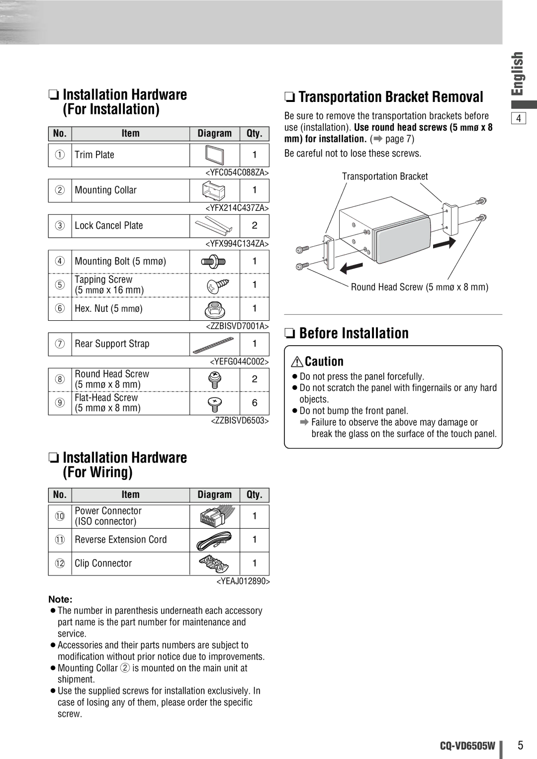
❏Transportation Bracket Removal
Be sure to remove the transportation brackets before use (installation). Use round head screws (5 mmø x 8
mm)for installation. (a page 7) Be careful not to lose these screws.
Transportation Bracket
Round Head Screw (5 mmø x 8 mm)
❏Before Installation
![]() Caution
Caution
¡Do not press the panel forcefully.
¡Do not scratch the panel with fingernails or any hard objects.
¡Do not bump the front panel.
aFailure to observe the above may damage or break the glass on the surface of the touch panel.
English
4
5