English
7
Electrical Connections
![]() Caution
Caution
¡This unit is designed for use in a car having a 12 V negative ground battery system.
¡Be sure to insulate any exposed wires from the car chassis. Bundle all cables and keep cable terminals free from any metal parts.
¡Note that if your car has a driving computer or a navigation computer, disconnecting the cable from the battery may clear the memory.
¡Run the cords avoiding the spots where the temperature can be extremely high.
5
6 | 8 m m M A X |
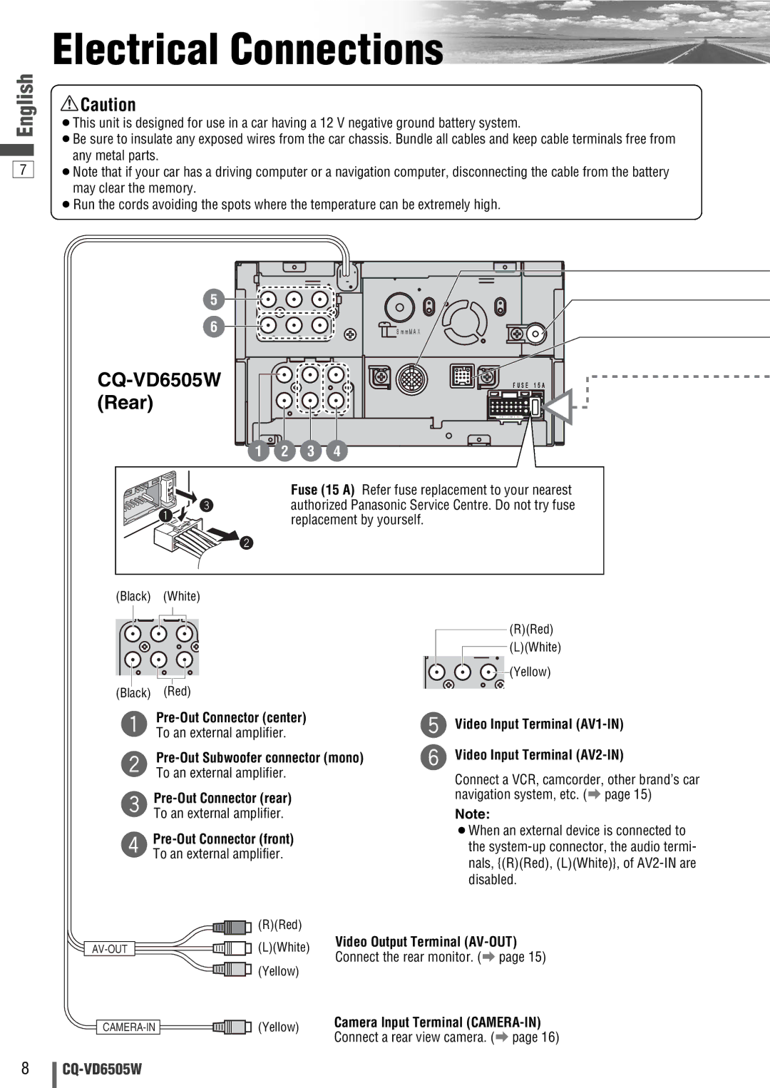
CQ-VD6505W (Rear)
1 2 3 4
F U S E 1 5 A
> P B T < J A M - S A a
Fuse (15 A) Refer fuse replacement to your nearest authorized Panasonic Service Centre. Do not try fuse replacement by yourself.
(Black) | (White) |
|
| |
|
|
| (R)(Red) | |
|
|
| (L)(White) | |
|
|
| (Yellow) | |
(Black) | (Red) |
|
| |
|
| t Video Input Terminal | ||
q To an external amplifier. |
| |||
| y Video Input Terminal | |||
w To an external amplifier. |
| Connect a VCR, camcorder, other brand’s car | ||
e |
| navigation system, etc. (a page 15) | ||
| Note: | |||
To an external amplifier. |
| |||
|
| ¡When an external device is connected to | ||
|
| |||
r To an external amplifier. |
| the | ||
|
|
| nals, {(R)(Red), (L)(White)}, of | |
|
|
| disabled. | |
| (R)(Red) |
|
| |
(L)(White) | Video Output Terminal | |||
Connect the rear monitor. (a page 15) | ||||
| (Yellow) | |||
|
|
| ||
(Yellow) | Camera Input Terminal | |||
Connect a rear view camera. (a page 16) | ||||
|
| |||
8
