16. Gas Conversion
WARNINGS: Procedures to adapt the boiler to the type of gas available must be carried out by a competent and responsible person. Components used to adapt it to the type of gas available must be genuine parts only.
Procedures:
•Check that the gas cock (30 on Section
4)fitted on the gas supply pipe is turned off and the appliance is switched off at the circuit breaker.
•Remove the front and side panels of the case (see the section 17.2 Annual Maintenance – Dismantelling the External Panels).
•Take off the lid of the sealed chamber.
•Remove the front panel of the
type of gas, replacing the burner injectors correctly.
•
•Extract the control panel as explained in the section 12.1 of this manual.
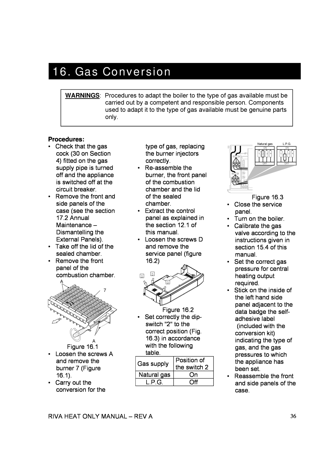
•Loosen the screws D and remove the service panel (figure 16.2)
Natural gas |
| L.P.G. |
ON |
| ON |
1 | 2 | 3 | 4 | 1 | 3 | 4 |
|
|
|
|
| 2 |
|
OFF | OFF |
Figure 16.3
• | Close the service |
| panel. |
• Turn on the boiler. | |
• | Calibrate the gas |
| valve according to the |
| instructions given in |
| section 15.4 of this |
| manual. |
• Set the correct gas | |
| pressure for central |
combustion chamber.
A
7
D
D
D
Figure 16.2
heating output |
required. |
• Stick on the inside of |
the left hand side |
panel adjacent to the |
data badge the self- |
A
Figure 16.1
•Loosen the screws A and remove the burner 7 (Figure 16.1).
•Carry out the conversion for the
•Set correctly the dip- switch "2" to the correct position (Fig. 16.3) in accordance with the following table.
Gas supply | Position of | |
the switch 2 | ||
| ||
Natural gas | On | |
L.P.G. | Off |
adhesive label |
(included with the |
conversion kit) |
indicating the type of |
gas, and the gas |
pressures to which |
the appliance has |
been set. |
• Reassemble the front |
and side panels of the |
case. |
RIVA HEAT ONLY MANUAL – REV A | 36 |
