11. Gas Pipe Connections
Gas supply piping is to be sized and installed properly in order to provide a supply of gas sufficient to meet the maximum demand without undue loss of pressure between the meter and the boiler. Consult with the National Fuel Gas Code ANSI Z223.1 for proper sizing of gas piping for various lengths and diameters.
Direction of flow
F
A
B
C
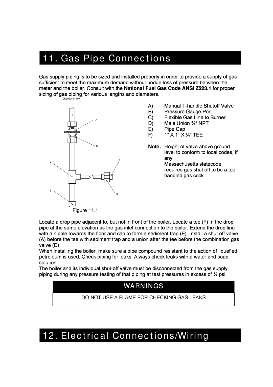
A)Manual
B)Pressure Gauge Port
C)Flexible Gas Line to Burner
D)Male Union ¾” NPT
E)Pipe Cap
F)1” X 1” X ¾” TEE
Note: Height of valve above ground level to conform to local codes, if any.
Massachusetts statecode requires gas shut off to be a tee handled gas cock.
E
D
Figure 11.1
Locate a drop pipe adjacent to, but not in front of the boiler. Locate a tee (F) in the drop pipe at the same elevation as the gas inlet connection to the boiler. Extend the drop line with a nipple towards the floor and cap to form a sediment trap (E). Install a shut off valve
(A)before the tee with sediment trap and a union after the tee before the combination gas valve (D).
When installing the boiler, make sure a pipe compound resistant to the action of liquefied petroleum is used. Check piping for leaks. Always check leaks with a water and soap solution.
The boiler and its individual
WARNINGS
DO NOT USE A FLAME FOR CHECKING GAS LEAKS
12. Electrical Connections/Wiring
RIVA HEAT ONLY MANUAL - REV A22
