TECHNICAL GUIDE | Cal. 5J32A |
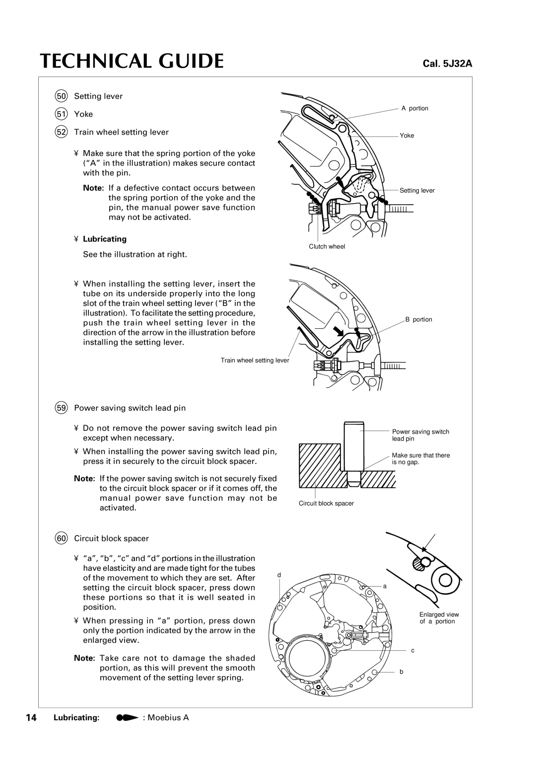
50 Setting lever
51 Yoke
52 Train wheel setting lever
•Make sure that the spring portion of the yoke
(“A” in the illustration) makes secure contact with the pin.
Note: If a defective contact occurs between the spring portion of the yoke and the pin, the manual power save function may not be activated.
•Lubricating
Clutch wheel
“A” portion
Yoke
Setting lever
See the illustration at right.
•When installing the setting lever, insert the tube on its underside properly into the long slot of the train wheel setting lever (“B” in the illustration). To facilitate the setting procedure, push the train wheel setting lever in the direction of the arrow in the illustration before installing the setting lever.
“B” portion
Train wheel setting lever
59 Power saving switch lead pin
•Do not remove the power saving switch lead pin except when necessary.
• When installing the power saving switch lead pin, press it in securely to the circuit block spacer.
Note: If the power saving switch is not securely fixed to the circuit block spacer or if it comes off, the manual power save function may not be
Power saving switch lead pin
Make sure that there is no gap.
activated.
Circuit block spacer
60Circuit block spacer
• “a”, “b”, “c” and “d” portions in the illustration
have elasticity and are made tight for the tubes
of the movement to which they are set. After | d | |
a | ||
setting the circuit block spacer, press down | ||
these portions so that it is well seated in |
| |
position. |
|
•When pressing in “a” portion, press down only the portion indicated by the arrow in the enlarged view.
Enlarged view of “a” portion
c
Note: Take care not to damage the shaded |
| |
portion, as this will prevent the smooth | b | |
movement of the setting lever spring. | ||
|
14 | Lubricating: | : Moebius A |