ASSEMBLY
ASSEMBLY
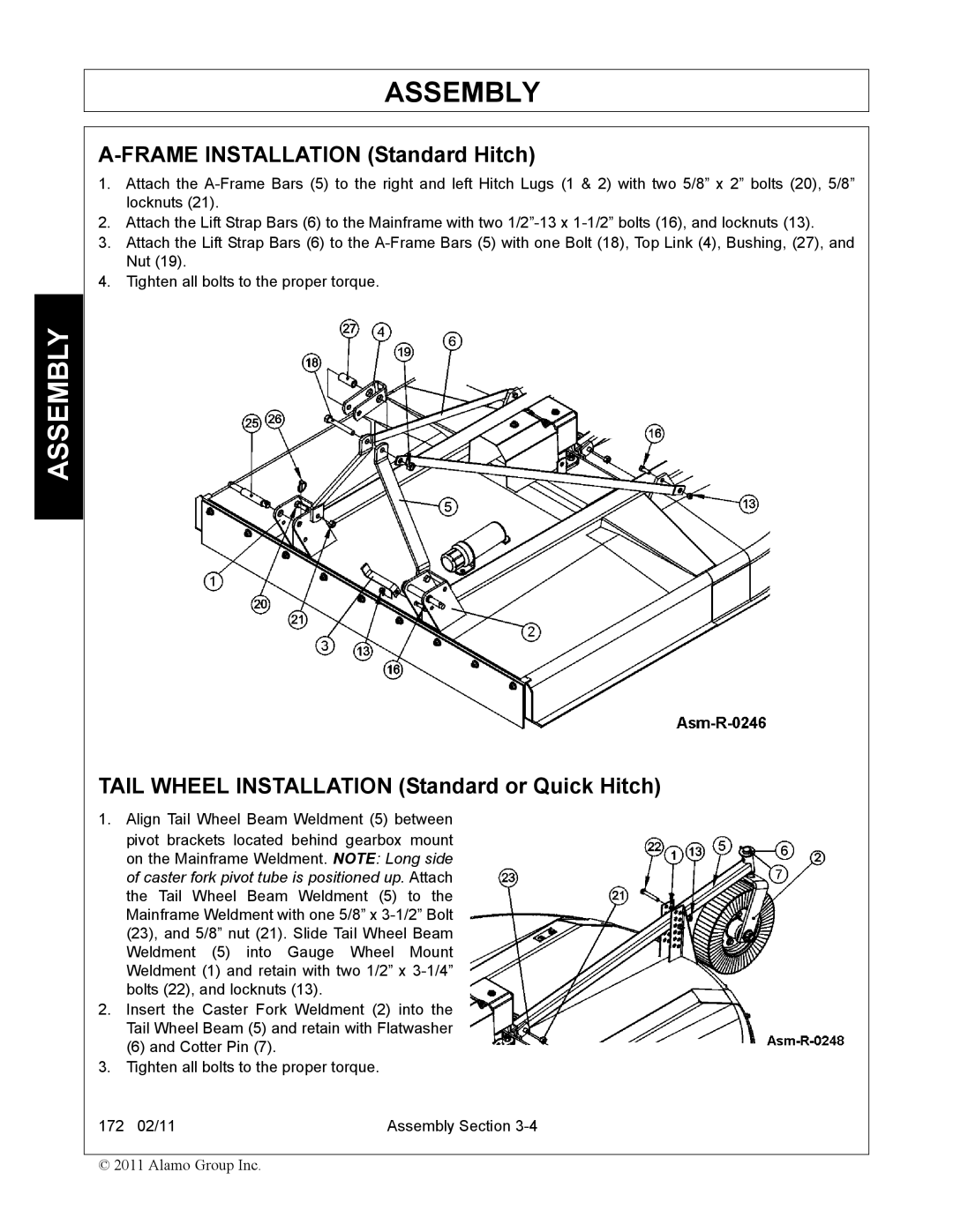
A-FRAME INSTALLATION (Standard Hitch)
1.Attach the
2.Attach the Lift Strap Bars (6) to the Mainframe with two
3.Attach the Lift Strap Bars (6) to the
4.Tighten all bolts to the proper torque.
TAIL WHEEL INSTALLATION (Standard or Quick Hitch)
1.Align Tail Wheel Beam Weldment (5) between
pivot brackets located behind gearbox mount on the Mainframe Weldment. NOTE: Long side of caster fork pivot tube is positioned up. Attach the Tail Wheel Beam Weldment (5) to the Mainframe Weldment with one 5/8” x
2.Insert the Caster Fork Weldment (2) into the Tail Wheel Beam (5) and retain with Flatwasher
(6) and Cotter Pin (7).
3.Tighten all bolts to the proper torque.
172 02/11 | Assembly Section |
© 2011 Alamo Group Inc.