Ver. 6.0U _ Sep 6, 2012
B) MODULE SPECIFIC INSTRUCTIONS
MECHANICAL INSTALLATION
There are several approved ways to mount these Sharp PV modules to a support structure. They may be mounted either using the bolt holes provided or using frame clamps (not provided).
To provide adequate ventilation, modules must be mounted such that there is a minimum 50 mm gap between the bottom of the module frame and the roof deck/ground surface.
Mounting Using Frame Bolt Holes (Figures 6)
The modules may be fastened to a support utilizing the four 9 mm diameter holes in the bottom of the frame and according to Figure 6. The module should be fastened with four (4) M8 (5/16") bolts. Recommended torque value is 12.5 Nm. This mounting method is designed to a static load of 2400 Pa (50.1 lbs/ft²). For your reference, please use the washer specified as below for the minimum requirement:
We recommended parts of the following specifications.
1) | Spring washer | 3) | Bolt |
| Material: Stainless Steel |
| Material: Stainless Steel |
| Diameter: M8 (5/16") |
| Diameter: M8 (5/16")×20 mm |
| Thickness: 2 mm (reference value) |
|
|
2) | Washer | 4) | Nut |
| Material: Stainless Steel |
| Material: Stainless Steel |
| Size: M8 (5/16") |
| Size: M8 (5/16") |
Thickness: 1.6 mm (reference value)
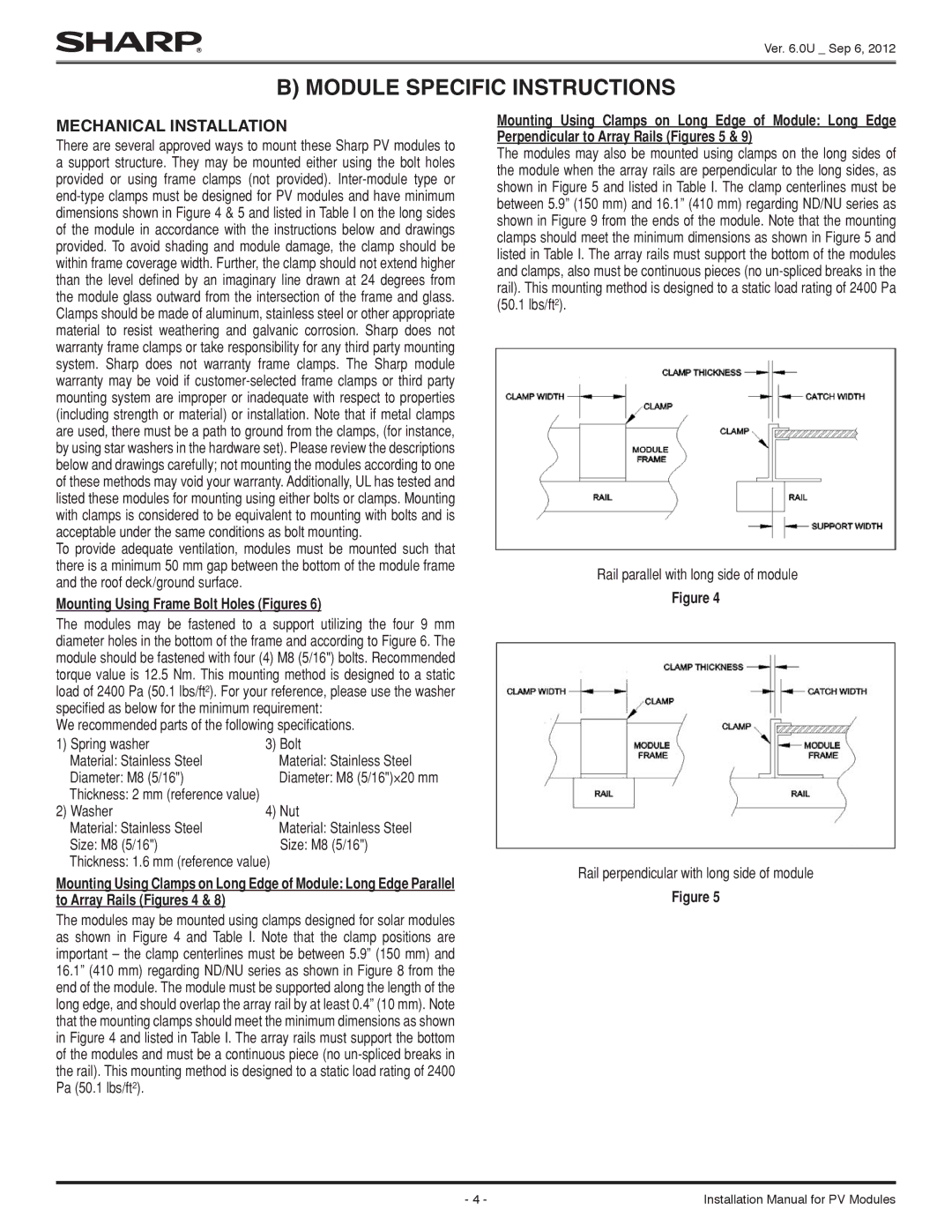
Mounting Using Clamps on Long Edge of Module: Long Edge Parallel to Array Rails (Figures 4 & 8)
The modules may be mounted using clamps designed for solar modules as shown in Figure 4 and Table I. Note that the clamp positions are important – the clamp centerlines must be between 5.9” (150 mm) and 16.1” (410 mm) regarding ND/NU series as shown in Figure 8 from the end of the module. The module must be supported along the length of the long edge, and should overlap the array rail by at least 0.4” (10 mm). Note that the mounting clamps should meet the minimum dimensions as shown in Figure 4 and listed in Table I. The array rails must support the bottom of the modules and must be a continuous piece (no
Mounting Using Clamps on Long Edge of Module: Long Edge Perpendicular to Array Rails (Figures 5 & 9)
The modules may also be mounted using clamps on the long sides of the module when the array rails are perpendicular to the long sides, as shown in Figure 5 and listed in Table I. The clamp centerlines must be between 5.9” (150 mm) and 16.1” (410 mm) regarding ND/NU series as shown in Figure 9 from the ends of the module. Note that the mounting clamps should meet the minimum dimensions as shown in Figure 5 and listed in Table I. The array rails must support the bottom of the modules and clamps, also must be continuous pieces (no
Rail parallel with long side of module
Figure 4
Rail perpendicular with long side of module
Figure 5
- 4 - | Installation Manual for PV Modules |