Assembly
Throttle Linkage and Ignition Leads
50-hour Maintenance
ASSEMBLY
Remove the Cylinder Cover.
1.Remove the spark plug boot.
2.Remove the two lower cylinder cover screws.
3.Loosen the top cylinder cover screw until the cover is free of the engine. (The top cylinder cover screw is captive). Lift the cylinder cover off of the engine.
See Figure 7.
Top
Cylinder
Cover
Screw
Spark Plug
Hex
Boot
Wrench
Lower Cylinder
Cover Screws
Figure 7
Connect the Throttle Cable.
1.Loop the ribbed cable tube to the top left side of the engine.
2.Install the black wire between the two cable adjuster nuts as shown. See Figure 8.
Ignition |
Leads |
Cable |
Adjuster |
Figure 8 |
3.Connect the
See Figure 9.
Figure 9 |
Every 50 hours of operation (more frequently in dusty or dirty conditions):
■Remove and clean the cylinder cover and clean dirt and debris from the cylinder cooling fins.
■Remove the sprocket cover and inspect the sprocket for excessive dirt, debris, or wear. Remove the guide bar and clean out the guide bar groove. If the sprocket is excessively worn, replace it with a new one. See Figure 32.
Inspect the
sprocket
Figure 32
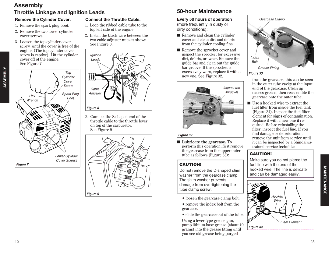
■Lubricate the gearcase. To perform this operation, first remove the gearcase from the upper outer tube as follows (Figure 33):
CAUTION!
Do not remove the
•loosen the gearcase clamp bolt.
•remove the index bolt from the gearcase.
•slide the gearcase out of the tube.
Using a
Gearcase Clamp
Index
Bolt
Grease Fitting
Figure 33
from the gearcase, this can be seen in the outer tube cavity at the input end of the gearcase. Clean up excess grease, then reassemble the gearcase onto the outer tube.
■Use a hooked wire to extract the fuel filter from inside the fuel tank (Figure 34). Inspect the fuel filter element for signs of contamination. Replace it with a new one if re- quired. Before reinstalling the filter, inspect the fuel line. If you find damage or deterioration, remove the unit from service until it can be inspected by a Shindaiwa- trained service technician.
CAUTION!
Make sure you do not pierce the fuel line with the end of the hooked wire. The line is delicate and can be damaged easily.
Hooked |
Wire |
Filter Element |
Figure 34 |
MAINTENANCE
12
25 |