General Maintenance
Installing and Adjusting the Bar and Chain
IMPORTANT!
MAINTENANCE, REPLACEMENT, OR REPAIR OF EMISSION CON- TROL DEVICES AND SYSTEM MAY BE PERFORMED BY ANY REPAIR ESTABLISHMENT OR INDIVIDUAL. HOWEVER, WARRANTY REPAIRS MUST BE PERFORMED BY A DEALER OR SERVICE CENTER AUTHORIZED BY SHINDAIWA KOGYO, LTD. AND USE OF PARTS THAT ARE NOT EQUIVALENT IN PERFORMANCE AND DURABILITY TO AUTHORIZED PARTS MAY IMPAIR THE EFFECTIVENESS OF THE EMISSION CONTROL SYSTEM
WARNING!
Before performing any mainte- nance, repair, or cleaning work on the unit, make sure the engine and cutting attachment are completely stopped. Disconnect the spark plug wire before performing service or maintenance work.
WARNING!
Installing The Chain
WARNING!
Never attempt to install, replace, or adjust the chain with the engine running.
WARNING!
The saw chain is very sharp. Wear gloves to protect your hands when handling.
NOTE:
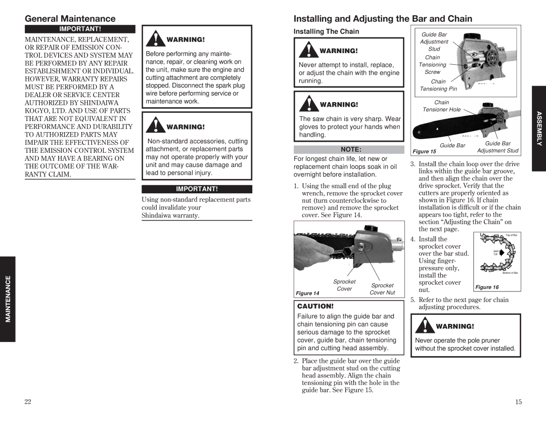
Guide Bar
Adjustment
Stud
Chain
Tensioning
Screw
Chain
Tensioning Pin
Chain
Tensioner Hole
| Guide Bar | Guide Bar | |
Figure 15 | Adjustment Stud | ||
|
ASSEMBLY
AND MAY HAVE A BEARING ON THE OUTCOME OF THE WAR- RANTY CLAIM.
may not operate properly with your unit and may cause damage and lead to personal injury.
IMPORTANT!
Using
Shindaiwa warranty.
For longest chain life, let new or replacement chain loops soak in oil overnight before installation.
1.Using the small end of the plug wrench, remove the sprocket cover nut (turn counterclockwise to remove) and remove the sprocket cover. See Figure 14.
3.Install the chain loop over the drive links within the guide bar groove, and then align the chain over the drive sprocket. Verify that the cutters are properly oriented as shown in Figure 16. If chain installation is difficult or if the chain appears too tight, refer to the section “Adjusting the Chain” on the next page.
| Sprocket | Sprocket | |
| Cover | ||
Figure 14 | Cover Nut | ||
|
4.Install the sprocket cover over the bar stud. Using finger- pressure only, install the sprocket cover nut.
Top of Bar |
BAR |
TIP |
Bottom of Bar |
Figure 16 |
MAINTENANCE
22
CAUTION!
Failure to align the guide bar and chain tensioning pin can cause serious damage to the sprocket cover, guide bar, chain tensioning pin and cutting head assembly.
2.Place the guide bar over the guide bar adjustment stud on the cutting head assembly. Align the chain tensioning pin with the hole in the guide bar. See Figure 15.
5.Refer to the next page for chain adjusting procedures.
WARNING!
Never operate the pole pruner without the sprocket cover installed.
15