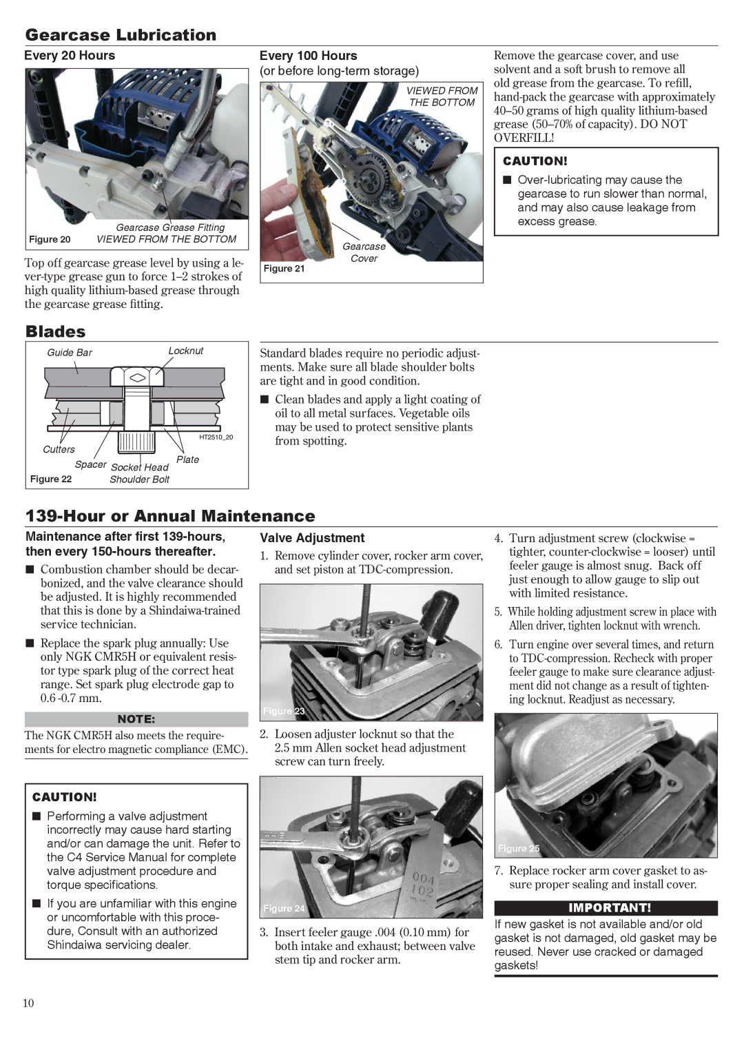
Gearcase Lubrication
Every 20 Hours
Gearcase Grease Fitting
Figure 20 VIEWED FROM THE BOTTOM
Top off gearcase grease level by using a le-
Every 100 Hours
(or before long-term storage)
VIEWED FROM
THE BOTTOM
Gearcase
Cover
Figure 21
Remove the gearcase cover, and use solvent and a soft brush to remove all old grease from the gearcase. To refill,
CAUTION!
n
Blades |
|
|
Guide Bar |
| Locknut |
|
| HT2510_20 |
Cutters |
| Plate |
Spacer Socket Head | ||
Figure 22 | Shoulder Bolt | |
Standard blades require no periodic adjust- ments. Make sure all blade shoulder bolts are tight and in good condition.
nClean blades and apply a light coating of oil to all metal surfaces. Vegetable oils may be used to protect sensitive plants from spotting.
139-Hour or Annual Maintenance
Maintenance after first
nCombustion chamber should be decar- bonized, and the valve clearance should be adjusted. It is highly recommended that this is done by a
nReplace the spark plug annually: Use only NGK CMR5H or equivalent resis- tor type spark plug of the correct heat range. Set spark plug electrode gap to 0.6
NOTE:
The NGK CMR5H also meets the require- ments for electro magnetic compliance (EMC).
CAUTION!
nPerforming a valve adjustment incorrectly may cause hard starting and/or can damage the unit. Refer to the C4 Service Manual for complete valve adjustment procedure and torque specifications.
nIf you are unfamiliar with this engine or uncomfortable with this proce- dure, Consult with an authorized Shindaiwa servicing dealer.
Valve Adjustment
1.Remove cylinder cover, rocker arm cover, and set piston at
Figure 23
2.Loosen adjuster locknut so that the 2.5 mm Allen socket head adjustment screw can turn freely.
Figure 24
3.Insert feeler gauge .004 (0.10 mm) for both intake and exhaust; between valve stem tip and rocker arm.
4.Turn adjustment screw (clockwise = tighter,
5.While holding adjustment screw in place with Allen driver, tighten locknut with wrench.
6.Turn engine over several times, and return to
Figure 25
7.Replace rocker arm cover gasket to as- sure proper sealing and install cover.
IMPORTANT!
If new gasket is not available and/or old gasket is not damaged, old gasket may be reused. Never use cracked or damaged gaskets!
10
