ASSEMBLING THE BLOWER (continued)
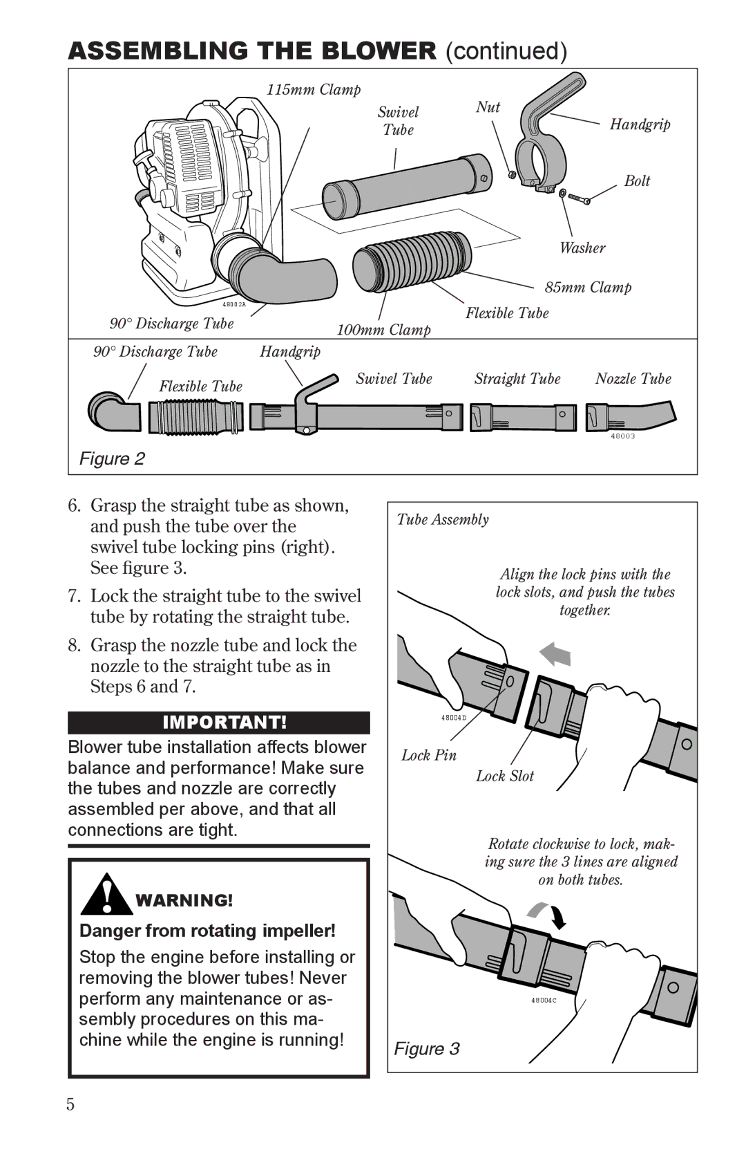
115mm Clamp
| Swivel | Nut | Handgrip |
|
| ||
| Tube |
| |
|
|
| |
|
|
| Bolt |
|
| Washer | |
|
| 85mm Clamp | |
48002A |
| Flexible Tube |
|
90° Discharge Tube | 100mm Clamp |
| |
|
| ||
|
|
| |
90° Discharge Tube | Handgrip |
|
|
Flexible Tube | Swivel Tube | Straight Tube | Nozzle Tube |
|
|
| |
| 48003 | |
Figure 2 |
| |
6. Grasp the straight tube as shown, | Tube Assembly | |
and push the tube over the | ||
| ||
swivel tube locking pins (right). |
| |
See figure 3. | Align the lock pins with the | |
7. Lock the straight tube to the swivel | lock slots, and push the tubes | |
tube by rotating the straight tube. | together. | |
| ||
8. Grasp the nozzle tube and lock the |
| |
nozzle to the straight tube as in |
| |
Steps 6 and 7. |
| |
IMPORTANT! | 48004D | |
Blower tube installation affects blower | Lock Pin | |
balance and performance! Make sure | ||
Lock Slot | ||
the tubes and nozzle are correctly | ||
| ||
assembled per above, and that all |
| |
connections are tight. | Rotate clockwise to lock, mak- | |
| ||
| ing sure the 3 lines are aligned | |
WARNING! | on both tubes. | |
| ||
Danger from rotating impeller! |
| |
Stop the engine before installing or |
| |
removing the blower tubes! Never |
| |
perform any maintenance or as- | 48004C | |
sembly procedures on this ma- |
| |
chine while the engine is running! | Figure 3 | |
|
5