A120S In-Line Switch User Guide
GENERAL
The A120S Accessory
The unit is supplied with a
OPERATION
Switch Function | Rotary Knob Position | |
|
| |
On/Off (Button remains down | Locking | |
until depressed a second time) |
| |
Momentary | ||
down only while depressed) | ||
| ||
|
|
Locking the Switch Button Down
The switch button can be locked down by following these steps.
1.Turn the rotary knob to locking.
2.Press the switch button down.
3.Turn the knob to Momentary.
The button will remain locked down until the knob is re- turned to locking and the button is depressed again.
SWITCH INSTALLATION AND WIRING
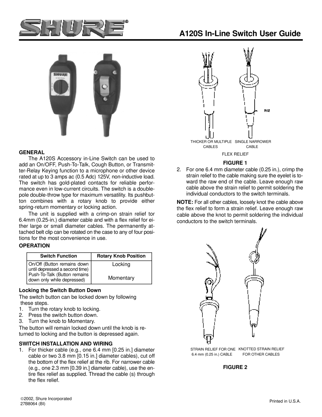
1.For thicker cable (e.g., one 6.4 mm [0.25 in.] diameter cable or two 3.8 mm [0.15 in.] diameter cables), cut off the bottom of the flex relief at the rib. For narrower cable (e.g., one 2.3 mm [0.39 in.] diameter cable), use the en- tire flex relief as supplied. Thread the cable (s) through the flex relief.
THICKER OR MULTIPLE SINGLE NARROWER
CABLESCABLE
FLEX RELIEF
FIGURE 1
2.For one 6.4 mm diameter cable (0.25 in.), crimp the strain relief to the cable making sure the eyelet is to- ward the raw end of the cable. Leave enough raw cable above the strain relief to permit soldering the individual conductors to the switch terminals.
NOTE: For all other cables, loosely knot the cable above the flex relief to form a strain relief. Leave enough raw cable above the knot to permit soldering the individual conductors to the switch terminals.
STRAIN RELIEF FOR ONE KNOTTED STRAIN RELIEF
6.4 mm (0.25 in.) CABLE | FOR OTHER CABLES |
FIGURE 2
2002, Shure Incorporated
27B8064 (BI)
Printed in U.S.A.