3.Solder the conductors to the switch terminals to ob- tain the desired function (see Figure 3 for switch configuration.) Take care no to leave long bare con- ductors that may bridge across terminals and make unintended connections.
NOTE: When the switch is used to make connections in the middle of a cable run, It is very important to preserve continuity in the cable shield. If a splice is necessary for this, be sure it is insulated from other terminals, or you may employ an unused switch terminal to make the con- nection. Leaving the shield discontinuous may cause undesirable hum in a circuit.
TERMINAL SIDE OF SWITCH
FIGURE 3
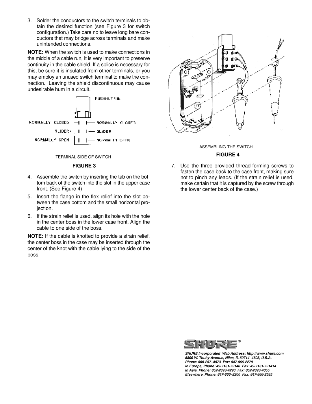
4.Assemble the switch by inserting the tab on the bot- tom back of the switch into the slot in the upper case front. (See Figure 4)
5.Insert the flange in the flex relief into the slot be- tween the case bottom and the small horizontal pro- jection.
6.If the strain relief is used, align its hole with the hole in the center boss in the lower case front. Align the cable to one side of the boss.
NOTE: If the cable is knotted to provide a strain relief, the center boss in the case may be inserted through the center of the knot with the cable lying to the side of the boss.
ASSEMBLING THE SWITCH
FIGURE 4
7.Use the three provided
SHURE Incorporated Web Address: http://www.shure.com 5800 W. Touhy Avenue, Niles, IL
In Europe, Phone:
In Asia, Phone:
Elsewhere, Phone:
