Configuration

Set Configuration DIP Switches

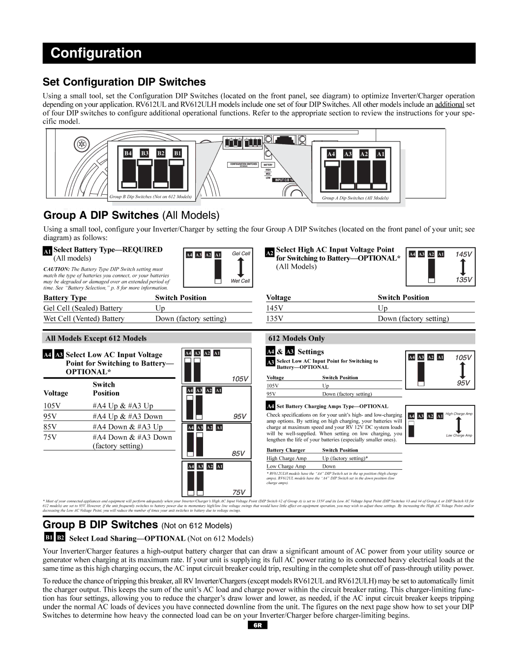
Using a small tool, set the Configuration DIP Switches (located on the front panel, see diagram) to optimize Inverter/Charger operation depending on your application. RV612UL and RV612ULH models include one set of four DIP Switches. All other models include an additional set of four DIP switches to configure additional operational functions. Refer to the appropriate section to review the instructions for your spe- cific model.

B4

B3

B2

B1

A4

A3

A2

A1


INPUT C/B


OUTPUT C/B 12A


Group B Dip Switches (Not on 612 Models)

Group A Dip Switches (All Models)


Group A DIP Switches (All Models)

Using a small tool, configure your Inverter/Charger by setting the four Group A DIP Switches (located on the front panel of your unit; see diagram) as follows:

A1 Select Battery Type—REQUIRED

(All models)

CAUTION: The Battery Type DIP Switch setting must match the type of batteries you connect, or your batteries may be degraded or damaged over an extended period of time. See “Battery Selection,” p. 8 for more information.

A4 A3 A2 A1

A2 Select High AC Input Voltage Point

for Switching to Battery—OPTIONAL*

(All Models)

A4 A3 A2 A1

Battery Type

Switch Position

Gel Cell (Sealed) Battery

Up

Wet Cell (Vented) Battery

Down (factory setting)

Voltage

Switch Position

145V

Up

135V

Down (factory setting)

All Models Except 612 Models

A4 A3 Select Low AC Input Voltage Point for Switching to Battery—

OPTIONAL*


Switch

Voltage

Position

A4 A3 A2 A1

A4 A3 A2 A1

612 Models Only

A4 & A3 Settings

A3 Select Low AC Input Point for Switching to Battery—OPTIONAL

Voltage

Switch Position

105V

Up

95V

Down (factory setting)

A4 A3 A2 A1

105V

#A4 Up & #A3 Up

95V

#A4 Up & #A3 Down

85V

#A4 Down & #A3 Up

75V

#A4 Down & #A3 Down


(factory setting)

A4 A3 A2 A1

A4 A3 A2 A1

A4 Set Battery Charging Amps Type—OPTIONAL

Check specifications on for your unit’s high- and low-charging amp options. By setting on high charging, your batteries will charge at maximum speed and your RV 12V DC system loads will be well-supplied. When setting on low charging, you lengthen the life of your batteries (especially smaller ones).

Battery Charger

Switch Position

High Charge Amp

Up (factory setting)*

Low Charge Amp

Down

*RV612ULH models have the “A4” DIP Switch set in the up position (high charge amps). RV612UL models have the “A4” DIP Switch set in the down position (low charge amps).

A4 A3 A2 A1 High Charge Amp

Low Charge Amp

*Most of your connected appliances and equipment will perform adequately when your Inverter/Charger’s High AC Input Voltage Point (DIP Switch #2 of Group A) is set to 135V and its Low AC Voltage Input Point (DIP Switches #3 and #4 of Group A or DIP Switch #3 for 612 models) are set to 95V. However, if the unit frequently switches to battery power due to momentary high/low line voltage swings that would have little effect on equipment operation, you may wish to adjust these settings. By increasing the High AC Voltage Point and/or decreasing the Low AC Voltage Point, you will reduce the number of times your unit switches to battery due to voltage swings.

Group B DIP Switches (Not on 612 Models)

B1 B2 Select Load Sharing—OPTIONAL (Not on 612 Models)

Your Inverter/Charger features a high-output battery charger that can draw a significant amount of AC power from your utility source or generator when charging at its maximum rate. If your unit is supplying its full AC power rating to its connected heavy electrical loads at the same time as this high charging occurs, the AC input circuit breaker could trip, resulting in the complete shut off of pass-through utility power.

To reduce the chance of tripping this breaker, all RVInverter/Chargers (except models RV612ULand RV612ULH) may be set to automatically limit the charger output. This keeps the sum of the unit’s AC load and charge power within the circuit breaker rating. This charger-limiting func- tion has four settings, allowing you to reduce the charger’s draw lower and lower, as needed, if the AC input circuit breaker keeps tripping under the normal AC loads of devices you have connected downline from the unit. The figures on the next page show how to set your DIP Switches to determine how heavy the connected load can be on your Inverter/Charger before charger-limiting begins.

6R

Page 6
Image 6
Tripp Lite 93-2182, 200310080 owner manual Set Configuration DIP Switches, Group a DIP Switches All Models

200310080, 93-2182 specifications

Tripp Lite, a renowned leader in power protection and connectivity solutions, designs high-quality products tailored to meet the demands of businesses and individuals alike. Among their extensive catalog is the Tripp Lite 93-2182,200310080 model, a powerhouse of technological innovation and pragmatic design.

The Tripp Lite 93-2182 is a versatile power distribution unit (PDU) that is engineered to provide efficient and reliable power to multiple devices. With a rack-mountable design, it is ideal for data centers, server rooms, and any setup where space is at a premium. Its sleek form factor allows it to blend seamlessly into existing infrastructure while maximizing power delivery and minimizing clutter.

One of the standout features of this PDU is its combination of multiple output options, including various NEMA outlets to accommodate a wide range of devices. This makes it an excellent solution for environments with diverse equipment requirements. Users can connect servers, networking equipment, and other critical devices without the need for additional power strips, promoting a cleaner workspace and reduced risk of tripping hazards.

In terms of technology, the Tripp Lite 93-2182 is equipped with surge protection capabilities that shield connected equipment from voltage spikes. This protection is crucial in safeguarding sensitive electronics from potential damage. Additionally, the PDU features built-in circuit breakers which provide over-current protection, ensuring the safe operation of connected devices.

Another significant characteristic of this model is its robust monitoring capabilities. Some versions come with options to monitor power consumption, which can help users make informed decisions regarding load balancing and energy efficiency. Furthermore, comprehensive management features allow for efficient remote monitoring, enhancing control over power distribution across the network.

The durability of the Tripp Lite 93-2182 is also noteworthy. Constructed with high-quality materials, it is designed to withstand the rigors of a dynamic data environment. The attention to detail in its design ensures that it operates under various conditions while maintaining optimal performance.

In summary, the Tripp Lite 93-2182,200310080 represents a culmination of advanced engineering and practical design. With its versatile output options, surge protection features, and robust monitoring capabilities, it is a reliable choice for anyone looking to optimize their power distribution needs, particularly in tight spaces where efficiency is paramount.