ENGLISH
12 dB and 18 dB Output Pads
Each DFR22 output has a 12 dB pad and an 18 dB pad that can be engaged through the software interface. Use these pads when con- necting the DFR22 to
NOTE: The Output meters indicate the signal level present at the
COMPUTER CONNECTIONS
RS-232 Connections
Connect the COM port on your computer to the
NOTE: Only the TX, RX, and GND pins need to be connected in order to communicate with the DFR22.
You can also connect a computer or control system to the
IMPORTANT: You CANNOT connect two PCs to the DFR22 at the same time. However, you CAN connect an AMX or Crestron sys- tem and a PC to the DFR22 at the same time.
RS-232 SERIAL PORT CONNECTION
Figure 9
COMPUTER | |
MALE CONNECTOR | |
TO COMPUTER |
|
DFR22 | |
TO DFR22 | FEMALE CONNECTOR |
Figure 10
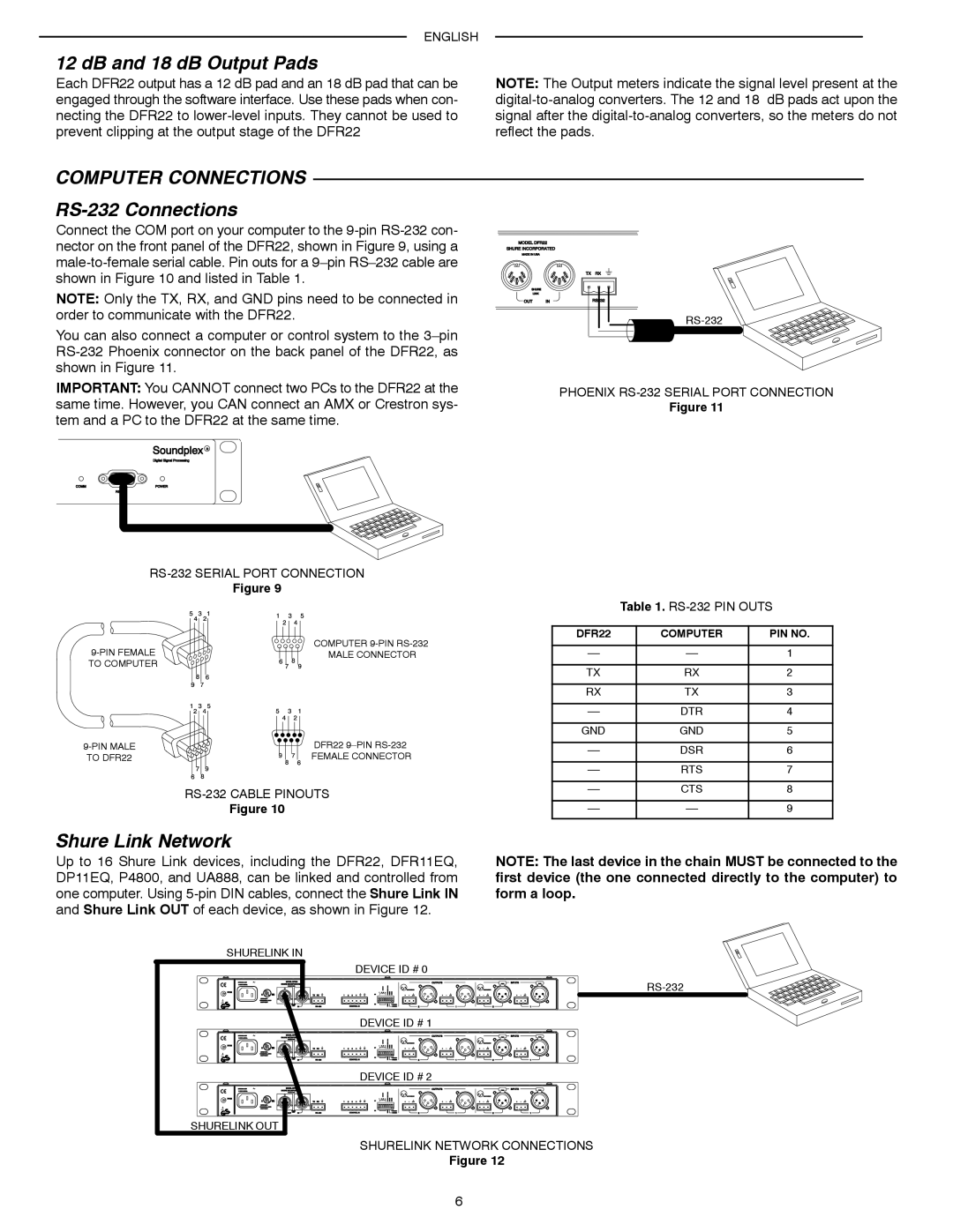
Shure Link Network
PHOENIX
Figure 11
Table 1.
DFR22 | COMPUTER | PIN NO. |
|
|
|
1 | ||
|
|
|
TX | RX | 2 |
|
|
|
RX | TX | 3 |
|
|
|
DTR | 4 | |
|
|
|
GND | GND | 5 |
|
|
|
DSR | 6 | |
|
|
|
RTS | 7 | |
|
|
|
CTS | 8 | |
|
|
|
9 | ||
|
|
|
Up to 16 Shure Link devices, including the DFR22, DFR11EQ, DP11EQ, P4800, and UA888, can be linked and controlled from one computer. Using
NOTE: The last device in the chain MUST be connected to the first device (the one connected directly to the computer) to form a loop.
SHURELINK IN
DEVICE ID # 0
DEVICE ID # 1
DEVICE ID # 2
SHURELINK OUT
SHURELINK NETWORK CONNECTIONS
Figure 12
6