
FP24 specifications
The Shure FP24 is a professional dual-channel field preamplifier designed for audio recording in a variety of environments. This compact and lightweight device is particularly favored by audio engineers and videographers for its high-quality sound capture and robust feature set. The FP24 is engineered to deliver precise audio performance and flexibility, making it an essential tool for filmmakers, sound recordists, and broadcast professionals.One of the standout features of the FP24 is its dual-channel capabilities, allowing users to connect two microphone sources simultaneously. This is particularly useful in capturing interviews or dialogues where two subjects are speaking. The device supports both low- and high-impedance microphones, including dynamic and condenser types, providing versatility for different recording scenarios.
The FP24 incorporates Shure's advanced preamp technology, delivering a wide dynamic range and low self-noise floor. This ensures that audio recordings maintain clarity and detail, even in challenging environments. With a frequency response that extends from 20 Hz to 20 kHz, the FP24 captures the full spectrum of sound, making it suitable for a wide range of applications, from dialogue to music.
Another significant characteristic of the FP24 is its phantom power capability. It can provide +48V of phantom power, essential for powering condenser microphones. Users have the option to toggle phantom power on or off for each channel independently, adding to the device’s user-friendly design.
The FP24 features a durable and rugged construction, well-suited for field use. It is housed in a chassis designed to withstand the rigors of on-location recording, providing confidence to users in various environmental conditions. Additionally, the swept gain controls offer precise adjustments, enabling users to finely tune their audio levels for optimal sound quality.
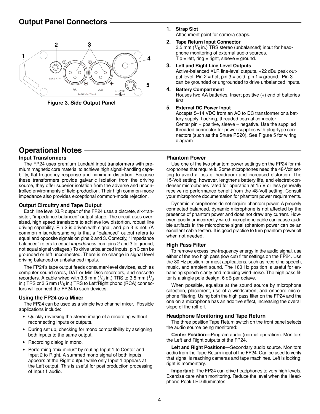
For connectivity, the FP24 is equipped with XLR outputs, allowing direct connection to cameras or audio recorders. This ensures a straightforward integration into any audio or video workflow. The device also comes with a variety of mounting options, making it easy to attach to camera rigs or field bags.
Overall, the Shure FP24 is a powerful and reliable field preamplifier. Its combination of high-quality audio performance, versatile connectivity, and robust build makes it an excellent choice for professionals seeking top-tier audio capture in demanding environments. Whether on location for a film shoot or in a recording studio, the FP24 delivers professional-grade sound quality that meets the needs of discerning audio engineers.