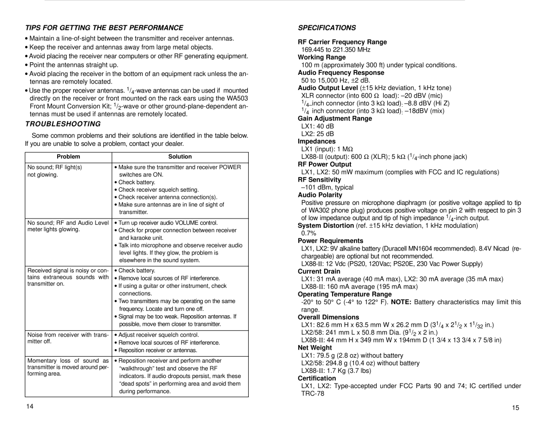
TIPS FOR GETTING THE BEST PERFORMANCE
•Maintain a
•Keep the receiver and antennas away from large metal objects.
•Avoid placing the receiver near computers or other RF generating equipment.
•Point the antennas straight up.
•Avoid placing the receiver in the bottom of an equipment rack unless the an- tennas are remotely located.
•Use the proper receiver antennas.
TROUBLESHOOTING
Some common problems and their solutions are identified in the table below. If you are unable to solve a problem, contact your dealer.
Problem | Solution |
|
|
No sound; RF light(s) | •Make sure the transmitter and receiver POWER |
not glowing. | switches are ON. |
| •Check battery. |
| •Check receiver squelch setting. |
| •Check receiver antenna connection(s). |
| •Make sure antennas are in line of sight of |
| transmitter. |
|
|
No sound; RF and Audio Level | •Turn up receiver audio VOLUME control. |
meter lights glowing. | •Check for proper connection between receiver |
| and karaoke unit. |
| •Talk into microphone and observe receiver audio |
| level lights. If they glow, the problem is |
| elsewhere in the sound system. |
|
|
Received signal is noisy or con- | •Check battery. |
tains extraneous sounds with | •Remove local sources of RF interference. |
transmitter on. | •If using a guitar or other instrument, check |
| connections. |
| •Two transmitters may be operating on the same |
| frequency. Locate and turn one off. |
| •Signal may be too weak. Reposition antennas. If |
| possible, move them closer to transmitter. |
|
|
Noise from receiver with trans- | •Adjust receiver squelch control. |
mitter off. | •Remove local sources of RF interference. |
| •Reposition receiver or antennas. |
|
|
Momentary loss of sound as | •Reposition receiver and perform another |
transmitter is moved around per- | ªwalkthroughº test and observe the RF |
forming area. | indicators. If audio dropouts persist, mark these |
| |
| ªdead spotsº in performing area and avoid them |
| during performance. |
|
|
14
SPECIFICATIONS
RF Carrier Frequency Range
169.445 to 221.350 MHz
Working Range
100 m (approximately 300 ft) under typical conditions.
Audio Frequency Response
50 to 15,000 Hz, ±2 dB.
Audio Output Level (±15 kHz deviation, 1 kHz tone) XLR connector (into 600 Ω load): ±20 dBV (mic)
1/4±inch connector (into 3 kΩ load): ±8.8 dBV (Hi Z)
1/4 inch connector (into 3 kΩ load): ±18dBV (mix)
Gain Adjustment Range
LX1: 40 dB
LX2: 25 dB
Impedances
LX1 (input): 1 MΩ
RF Power Output
LX1, LX2: 50 mW maximum (complies with FCC and IC regulations)
RF Sensitivity
±101 dBm, typical
Audio Polarity
Positive pressure on microphone diaphragm (or positive voltage applied to tip of WA302 phone plug) produces positive voltage on pin 2 with respect to pin 3 of low impedance output and tip of high impedance
System Distortion (ref. ±15 kHz deviation, 1 kHz modulation) 0.7%
Power Requirements
LX1, LX2: 9V alkaline battery (Duracell MN1604 recommended). 8.4V Nicad (re- chargeable) are optional but not recommended.
Current Drain
LX1: 31 mA average (40 mA max), LX2: 30 mA average (35 mA max)
Operating Temperature Range
Overall Dimensions
LX1: 82.6 mm H x 63.5 mm W x 26.2 mm D (31/4 x 21/2 x 11/32 in.)
LX2/58: 241 mm L x 50.8 mm Dia. (91/2 x 2 in.)
Net Weight
LX1: 79.5 g (2.8 oz) without battery
LX2/58: 294.8 g (10.4 oz) without battery
Certification
LX1, LX2:
15
