ADVANCED FUNCTIONS
The SCM810's Advanced Functions are recommended only for those who are technically knowledgeable and familiar with audio
electronics.
LOGIC CONNECTION SPECIFICATIONS
The logic functions of the SCM810 expand the mixer's range of installation and control options. Logic can be used for everything from simple cough switches to elaborate
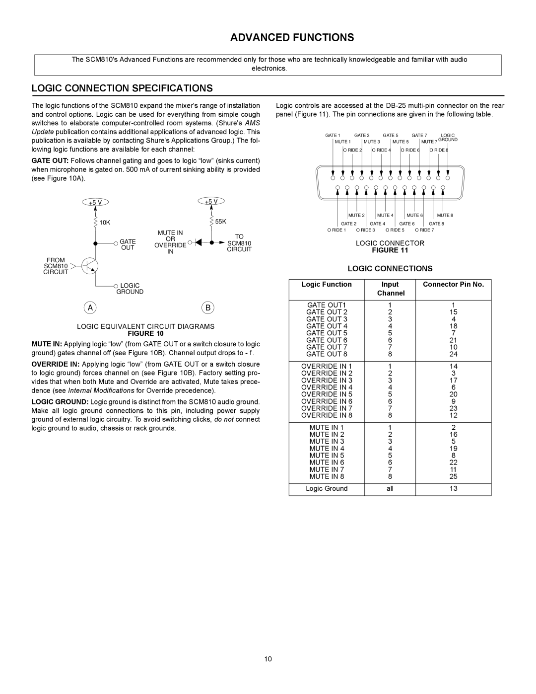
GATE OUT: Follows channel gating and goes to logic “low” (sinks current) when microphone is gated on. 500 mA of current sinking ability is provided (see Figure 10A).
+5 V |
| +5 V | |
10K |
| 55K | |
| MUTE IN | TO | |
GATE | OR | ||
SCM810 | |||
OVERRIDE | |||
OUT | CIRCUIT | ||
IN | |||
|
| ||
FROM |
|
| |
SCM810 |
|
| |
CIRCUIT |
|
| |
LOGIC |
|
| |
GROUND |
|
| |
A |
| B |
LOGIC EQUIVALENT CIRCUIT DIAGRAMS
FIGURE 10
MUTE IN: Applying logic “low” (from GATE OUT or a switch closure to logic ground) gates channel off (see Figure 10B). Channel output drops to
OVERRIDE IN: Applying logic “low” (from GATE OUT or a switch closure to logic ground) forces channel on (see Figure 10B). Factory setting pro- vides that when both Mute and Override are activated, Mute takes prece- dence (see Internal Modifications for Override precedence).
LOGIC GROUND: Logic ground is distinct from the SCM810 audio ground. Make all logic ground connections to this pin, including power supply ground of external logic circuitry. To avoid switching clicks, do not connect logic ground to audio, chassis or rack grounds.
Logic controls are accessed at the
GATE 1 |
| GATE 3 |
| GATE 5 |
| GATE 7 |
| LOGIC | |||||||||
| MUTE 1 |
| MUTE 3 |
| MUTE 5 |
| MUTE 7 GROUND | ||||||||||
|
|
|
| ||||||||||||||
|
| O’RIDE 2 |
|
| O’RIDE 4 |
|
| O’RIDE 6 |
|
| O’RIDE 8 |
|
| ||||
|
|
|
|
|
|
|
|
|
| ||||||||
|
|
|
|
|
|
|
|
|
|
|
|
|
|
|
|
|
|
|
|
|
|
|
|
|
|
|
|
|
|
|
|
|
|
|
|
|
|
|
|
|
|
|
|
|
|
|
|
|
|
|
|
|
|
MUTE 2 | MUTE 4 | MUTE 6 | MUTE 8 | |||
GATE 2 |
| GATE 4 |
| GATE 6 |
| GATE 8 |
O’RIDE 1 | O’RIDE 3 | O’RIDE 5 | O’RIDE 7 | |||
LOGIC CONNECTOR
FIGURE 11
LOGIC CONNECTIONS
Logic Function | Input | Connector Pin No. |
| Channel |
|
|
|
|
GATE OUT1 | 1 | 1 |
GATE OUT 2 | 2 | 15 |
GATE OUT 3 | 3 | 4 |
GATE OUT 4 | 4 | 18 |
GATE OUT 5 | 5 | 7 |
GATE OUT 6 | 6 | 21 |
GATE OUT 7 | 7 | 10 |
GATE OUT 8 | 8 | 24 |
|
|
|
OVERRIDE IN 1 | 1 | 14 |
OVERRIDE IN 2 | 2 | 3 |
OVERRIDE IN 3 | 3 | 17 |
OVERRIDE IN 4 | 4 | 6 |
OVERRIDE IN 5 | 5 | 20 |
OVERRIDE IN 6 | 6 | 9 |
OVERRIDE IN 7 | 7 | 23 |
OVERRIDE IN 8 | 8 | 12 |
|
|
|
MUTE IN 1 | 1 | 2 |
MUTE IN 2 | 2 | 16 |
MUTE IN 3 | 3 | 5 |
MUTE IN 4 | 4 | 19 |
MUTE IN 5 | 5 | 8 |
MUTE IN 6 | 6 | 22 |
MUTE IN 7 | 7 | 11 |
MUTE IN 8 | 8 | 25 |
|
|
|
Logic Ground | all | 13 |
|
|
|
10
