
SIMATIC PC Adapter TS Adapter specifications
The Siemens SIMATIC PC Adapter TS Adapter is an essential tool for integrating PC-based systems with Siemens automation equipment. This versatile interface enables seamless communication between PCs and programmable logic controllers (PLCs), facilitating efficient data exchange in industrial settings. The adapter is particularly popular for its ability to support various protocols, ensuring widespread compatibility with different Siemens devices.One of the primary features of the SIMATIC PC Adapter TS is its capability to connect to a multitude of Siemens PLCs, such as S7-1200, S7-1500, and S7-300 series, among others. This makes it a robust solution for users across diverse industries who require reliable communication between their PC systems and PLCs.
The TS Adapter utilizes the standardized Siemens communication protocols, including S7 protocol, which allows for fast data transfer rates and reduces any latency that could impact automation processes. The adapter can seamlessly support multiple connections, enabling multiple PCs to access the same PLC simultaneously. This promotes collaborative operation and enhances productivity in industrial applications.
Another notable technology incorporated into the SIMATIC PC Adapter TS is its USB connectivity. The USB interface allows for easy connection to various PC systems without the need for additional hardware. This plug-and-play functionality simplifies setup and reduces downtime during installation, making it an attractive choice for engineers and technicians.
The adapter is designed to be highly portable, with a compact form factor that can easily fit into laptop bags or toolboxes. This portability ensures that it can be utilized in different work environments, from factory floors to engineering offices, ensuring maximum flexibility.
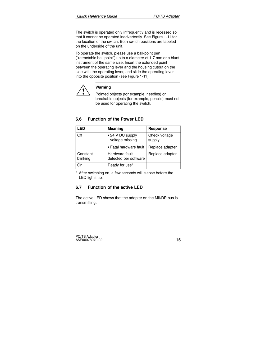
The characteristics of the SIMATIC PC Adapter TS include a sturdy construction that ensures durability in rugged industrial environments. It is also designed with user-friendly features, such as LED indicators that provide real-time feedback on the connection status and data transmission activity.
In conclusion, the Siemens SIMATIC PC Adapter TS Adapter is an indispensable tool for professionals seeking efficient communication between PC systems and Siemens PLCs. With its robust features, reliable connectivity, and ease of use, it plays a critical role in enhancing automation processes and driving productivity in various industrial applications.