V DANGER

Hazardous voltage.

Will cause death or serious injury.

Keep Out.

Qualified personnel only.

Disconnect and lock off all power before working on this equipment.

VCAUTION

CONDUCTING DIELECTRIC AND/OR HI-POTENTIAL TESTING WILL CAUSE INTERNAL DAMAGE TO TPS3 UNIT.

Do not perform dielectric or high potential

tests with the TPS3 unit installed.

TPS3 01 Installation Instructions for: Lighting Panelboards Type P1, P2, P3

If model number includes W option suffix, additional instructions follow

The following instructions are for the installation of the Siemens TPS3 01 and L1 SPD modules in Siemens Type P1 lighting panelboard. All hardware is supplied for complete installation of the TPS3 module. See page 2, Table 1 for Catalog numbers.

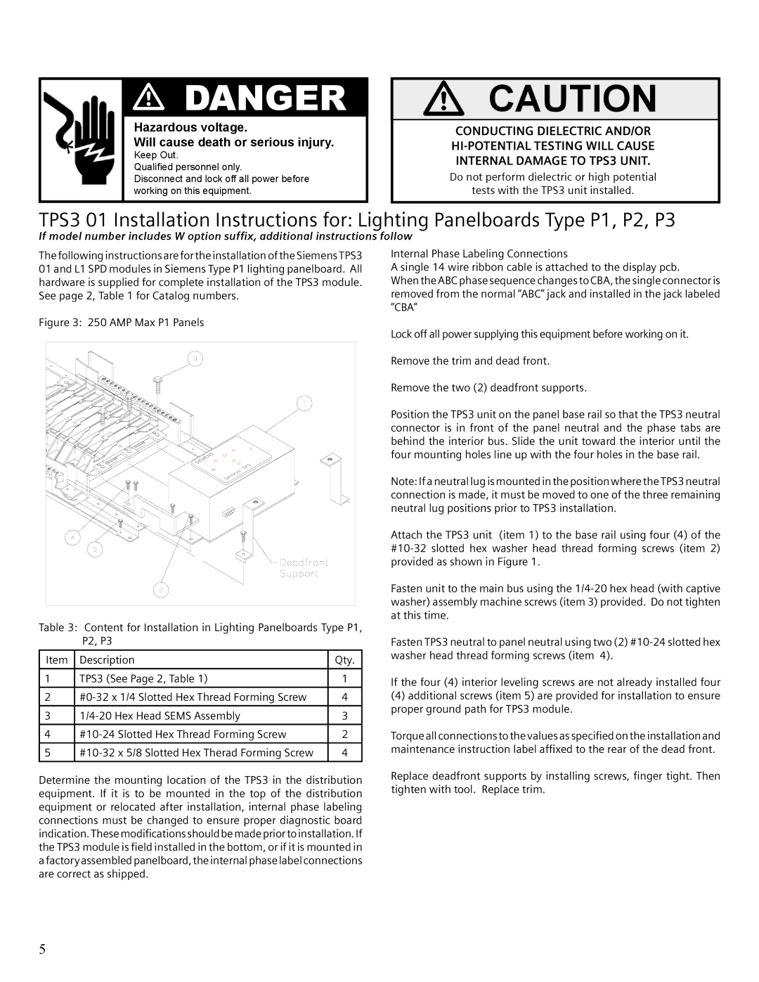
Figure 3: 250 AMP Max P1 Panels

Table 3: Content for Installation in Lighting Panelboards Type P1, P2, P3

Item

Description

Qty.


1

TPS3 (See Page 2, Table 1)

1


2

#0-32 x 1/4 Slotted Hex Thread Forming Screw

4


3

1/4-20 Hex Head SEMS Assembly

3


4

#10-24 Slotted Hex Thread Forming Screw

2


5

#10-32 x 5/8 Slotted Hex Therad Forming Screw

4


Internal Phase Labeling Connections

A single 14 wire ribbon cable is attached to the display pcb.

When the ABC phase sequence changes to CBA, the single connector is removed from the normal “ABC” jack and installed in the jack labeled “CBA”

Lock off all power supplying this equipment before working on it.

Remove the trim and dead front.

Remove the two (2) deadfront supports.

Position the TPS3 unit on the panel base rail so that the TPS3 neutral connector is in front of the panel neutral and the phase tabs are behind the interior bus. Slide the unit toward the interior until the four mounting holes line up with the four holes in the base rail.

Note: If a neutral lug is mounted in the position where the TPS3 neutral connection is made, it must be moved to one of the three remaining neutral lug positions prior to TPS3 installation.

Attach the TPS3 unit (item 1) to the base rail using four (4) of the #10-32 slotted hex washer head thread forming screws (item 2) provided as shown in Figure 1.

Fasten unit to the main bus using the 1/4-20 hex head (with captive washer) assembly machine screws (item 3) provided. Do not tighten at this time.

Fasten TPS3 neutral to panel neutral using two (2) #10-24 slotted hex washer head thread forming screws (item 4).

If the four (4) interior leveling screws are not already installed four

(4)additional screws (item 5) are provided for installation to ensure proper ground path for TPS3 module.

Torque all connections to the values as specified on the installation and maintenance instruction label affixed to the rear of the dead front.

Determine the mounting location of the TPS3 in the distribution equipment. If it is to be mounted in the top of the distribution equipment or relocated after installation, internal phase labeling connections must be changed to ensure proper diagnostic board indication. These modifications should be made prior to installation. If the TPS3 module is field installed in the bottom, or if it is mounted in a factory assembled panelboard, the internal phase label connections are correct as shipped.

Replace deadfront supports by installing screws, finger tight. Then tighten with tool. Replace trim.

5

Page 8
Image 8
Siemens TPS3 user manual Hazardous voltage Will cause death or serious injury

TPS3 specifications

Siemens TPS3 is a sophisticated technology advancement that has significantly impacted the field of industrial automation. As part of Siemens’ portfolio of control systems, TPS3 is designed to enhance process efficiency, improve accuracy in operations, and ensure greater reliability and flexibility across various industrial sectors.

One of the key features of the Siemens TPS3 is its modular architecture. This modularity allows users to customize the system according to their specific needs and operational requirements. Each module can be added or removed with ease, facilitating the scalability of operations. This flexibility is critical for businesses aiming to adapt their capacity based on fluctuating market demands.

The TPS3 employs state-of-the-art control technologies, integrating advanced algorithms for real-time data processing and control. This capability enables operators to achieve precise control over processes, ensuring that production runs smoothly and meets quality standards. Advanced predictive maintenance features are also embedded within the system, allowing for the minimization of downtime and optimization of maintenance schedules through data analytics.

Another significant characteristic of the TPS3 is its user-friendly interface. The intuitive design allows operators to easily monitor and manage processes through graphical displays and straightforward navigation. This usability reduces the learning curve for new staff and increases overall operational efficiency.

Siemens emphasizes connectivity in the TPS3, with robust support for Industry 4.0 principles. The system can seamlessly integrate with IoT devices and other digital platforms, enabling extensive data collection and analytics. This connectivity enhances decision-making by providing insights into process performance and resource utilization.

Security is also a critical aspect of the TPS3, with built-in features that protect against cyber threats. These security measures include encrypted communication protocols and robust firewall systems to safeguard sensitive operational data.

Overall, the Siemens TPS3 stands out for its modular design, real-time control capabilities, user-friendly interface, strong connectivity features, and commitment to security. These characteristics make it a potent tool for modern industries seeking to optimize their processes, reduce costs, and adapt to the ever-evolving technological landscape. With its comprehensive feature set, the TPS3 is poised to drive greater efficiency and innovation in the realm of industrial automation.