![]() 7
7
INSTALLATION
The Manifold Unit
Determine the most practical
1.Place the manifold and tank in the selected locations. If desired, the #6 self tapping screws may be used to secure the manifold unit in position by means of the top rear and bottom lip mounting holes.
2.Take the unused portion of the 3/8" white tubing and insert one end firmly into the 3/8" (larg- est) connector on the top of the manifold unit.
3.Extend the 3/8" white tubing from the manifold unit to the tank valve. Leave enough slack in the tubing to allow the unit to be removed from the installed location for servicing. Cut off the excess and insert the 3/8" tube into the
4.Extend the 1/4" yellow tubing from the faucet unit to the manifold. Leave enough slack in the tubing to allow the unit to be removed from the installed location for servicing. Cut off the excess and firmly insert the tubing into the corresponding yellow drain connection located on the mani- fold.
5.Extend the 3/8" blue tubing from the faucet unit to the manifold. Leave enough slack in the tubing to allow the unit to be removed from the installed location for servicing. Cut off the excess and firmly insert the tubing into the corresponding blue product water connection located on the manifold.
6.Extend the green tubing from the feed connector valve to the manifold. Leave enough slack in the tubing to allow the unit to be removed from the installed location for servicing. Cut off the excess and firmly insert the tubing into the corresponding green feed connection located on the manifold.
7.Obtain the Shutoff Warning label and affix it to the manifold unit so that it is directly visible. The Sierra system is now connected and ready for initial test and preparation.
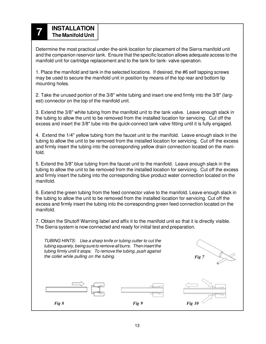
TUBING HINTS: Use a sharp knife or tubing cutter to cut the |
|
tubing squarely, being sure to remove all burrs. Then insert the |
|
tubing firmly until it stops. To remove the tubing, push against |
|
the collet while pulling on the tubing. | Fig 7 |
Fig 8 | Fig 9 | Fig 10 |
13
