ToolStick-F321DC
6.4. Viewing and Modifying Registers
All registers on the device can be viewed and modified when the device is in a halted state. The registers are grouped together according to which peripheral or part of hardware they belong. As an example, this guide shows how to open the ADC0 Debug Window and disable the ADC0 directly from the IDE.
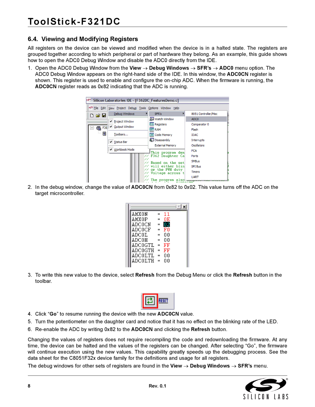
1.Open the ADC0 Debug Window from the View → Debug Windows → SFR’s → ADC0 menu option. The ADC0 Debug Window appears on the
2.In the debug window, change the value of ADC0CN from 0x82 to 0x02. This value turns off the ADC on the target microcontroller.
3.To write this new value to the device, select Refresh from the Debug Menu or click the Refresh button in the toolbar.
4.Click “Go” to resume running the device with the new ADC0CN value.
5.Turn the potentiometer on the daughter card and notice that it has no effect on the blinking rate of the LED.
6.
Changing the values of registers does not require recompiling the code and redownloading the firmware. At any time, the device can be halted and the values of the registers can be changed. After selecting “Go”, the firmware will continue execution using the new values. This capability greatly speeds up the debugging process. See the data sheet for the C8051F32x device family for the definitions and usage for all registers.
The debug windows for other sets of registers are found in the View → Debug Windows → SFR’s menu.
8 | Rev. 0.1 |