
MC-8 specifications
The Simaudio MC-8 stands as a hallmark of high-end audio amplification, designed to cater to audiophiles seeking pristine sound quality and remarkable power delivery. This multichannel amplifier is a part of Simaudio’s Moon Evolution line, which is known for its commitment to maintaining musical fidelity across various playback systems.One of the MC-8’s standout features is its ability to deliver an impressive output of 200 watts per channel into 8-ohm loads. This robust power ensures that it can effortlessly drive a range of speakers, from compact models to larger floor-standing types, all while maintaining excellent dynamic range and detail. The amplifier operates in Class A/B mode, which strikes a perfect balance between sound quality and efficiency, providing users with a warm and inviting listening experience.
The MC-8 is built with advanced technologies that enhance its performance. For instance, it employs a proprietary circuit design that minimizes distortion and improves overall clarity across the frequency spectrum. Furthermore, it integrates a power supply utilizing high-capacity toroidal transformers, which maximizes energy delivery while reducing noise, ensuring a clean signal path.
Another characteristic that sets the MC-8 apart is the focus on modularity; it features a flexible architecture that enables future upgrades and enhances longevity. This means users can adapt the amplifier to the changing landscape of their audio preferences and technology advancements over time.
Additionally, the MC-8 is equipped with a sophisticated thermal management system, which not only optimizes performance but also ensures reliability during extended use. It is engineered with attention to detail, featuring a sturdy chassis that minimizes vibrations and external interference, contributing to overall sound purity.
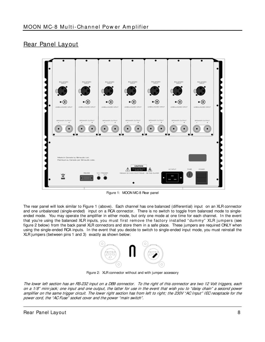
In terms of connectivity, the MC-8 boasts multiple inputs, allowing for versatile system integration. This includes balanced XLR inputs, which are essential for reducing noise in longer cable runs, alongside traditional RCA inputs for compatibility with a wide range of sources.
The Simaudio MC-8 stands out not only for its technical specifications but also for its aesthetic appeal, showcasing a modern design that complements any high-end audio setup. Combining power, flexibility, and superb musicality, the MC-8 truly represents an excellent choice for any serious audio enthusiast looking to elevate their listening experience.